Fax to David Jonsson, Upsala, Sweden (internet:
david@ibg.uu.se)
October 30, 1995
Dear David:
Confirming that I received your nice fax of Oct 6; have just been so swamped
here that things have been impossible. Also received your latest fax today.
Thanks for the statistics; looks as if at least a few persons are interested
in this material. Will try to give you a short update.
Our overunity work continues to go well, and we are making progress although
severely hampered by lack of funds and laboratory equipment. (We have about
a $30,000 laboratory; we need about a $150,000 lab). The best thing we have
found - where the semiconductors self-target with each other at
instantaneous velocity (superluminal tunneling) - requires a better lab than
we possess in order to resolve the instabilities. We demonstrated such
circuits two years ago that produced substantial overunity, but promptly
blew themselves up because of unstability. Nonetheless, that is the wave of
the future, because eventually we will do it with just a few semiconductors
and ordinary switching components. But first, rigid stabilizing methods have
to be worked out. We know what the problem is, and how to go about solving
it, but do not have the physical technical facilities that are required. So
we have turned to other overunity methods, which are beginning to look very
promising. Just now we are doing much of our work on a SPICE-type simulator.
It is much easier to change parameters and "blow up the simulation" than it
is to blow up actual circuits.
Also we have particulary made great strides in our theoretical
understanding. Presently I feel that we have finally produced a legitimate
theory of electrical overunity machines, and we will be publishing much of
that in the future as soon as our patent application situation is completed.
Simply put, there is no longer any doubt as to the precise mechanisms
involved in overunity coefficient of performance.
Our work in correcting electromagnetic theory also goes well, particularly
with respect to my 1973 statement of the actual mechanism that generates the
flow of time. That has now been extended and refined. As with other EM
mechanisms, this one is also subject to direct engineering.
My colleagues and I have now filed some four patents, and are in process of
preparing two more. One of these is on overunity process and apparatus that
we have shown to work both theoretically and by direct simulation. The other
is a discovery of what appears to be a totally new law of nature. This
latter discovery enables energy mechanisms of such ramifications and power
that one's mind is literally numbed at the prospect. It is a totally
different way of addressing the energy problem.
However, these patent applications we have filed are formidable documents,
most running to 200 pages or more, and they have required enormous effort to
write and submit. It is in these documents that we have advanced the theory
of electrical overunity machines. At any rate, we are now in patent pending
status on several major apparatuses and processes for electrical overunity
machines, and on room temperature superconductivity (which turned out to be
rather straightforward, once dq/dt-blocking is applied). One simply
transfers the energy across the superconducting section as S-flow, rather
than as J�. That is, one makes J=0, but in a 2-line conductor
section so that d�/dt
![]() 0 and S
0 and S![]() 0.
0.
We have also successfully resolved the controversy that has gone on in the
literature for a century with respect to the flow of energy in electrical
circuits; i.e. the Poynting S-flow theory of Poynting and Heaviside. (Heaviside's
version is much better than the accepted Poynting version, because it
includes electrogravitation as well). As you may know, Poynting theory has
not been very successfully applied to circuits of any but the simplest
configurations. It is used easily and extensively, however, in systems that
radiate EM energy into space. Literally, electrical engineers do not know
how the flow of energy is evoked from their circuits, and how it flows in
their circuits. They are taught to track only the minuscule losses and
scatterings from that energy flow.
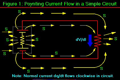
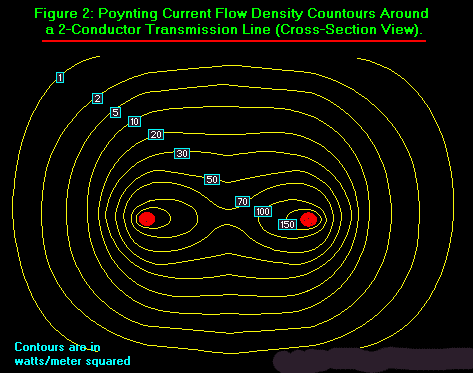
There has been a continuing discussion (and disagreement) in the literature, and much of the material in those papers is seriously flawed, and some is downright wrong. Most EM textbooks shy away from the Poynting flow in circuits; Jackson, e.g., does not mention it. Most texts show a simple circuit or two, work out one or two simple examples, state that "See! This energy flow stuff works also!" and then the authors get the heck out of that "bottomless pit" with obvious relief. Of all the texts I have found, Kraus (4th edition) tries the hardest, and only contains a minor error or two. I enclose Figures 1 and 2 to show how the S-flows actually run in a simple circuit, including from the vacuum and back to the vacuum.
Interestingly, the Slepian vector J� is the energy collected by the circuit from the Poynting flow S. S-flow is outside the conductors and very rapid, while J is totally internal to the conductor and incredibly sluggish. When one works it all out, one finds that -- on the average -- a typical circuit collects as J� some 10-13 of the mightly energy flow S that is evoked by the source along its conductors in the external circuit! So our modern circuitry is the most inefficient energy collector imaginable. This justifies my former statement that a flashlight battery could in theory power a battleship. However, one would have to increase the energy collection efficiency of the external circuit connected to the battery, quite a few times over!
It would appear that there are ways of doing that; and those ways produce
overunity coefficient of performance. Even so, one is still collecting only
a very, very small fraction of the actual raging energy flow that the source
extracts from the vacuum and send down the conductors.
Here is a new one for you to ponder.
It is not necessary to discover how to build a "free energy source". That is
all that we have ever built anyway! Every generator and every battery is
already a true, free energy source. A source does not add a single electron
to the circuit; it does not furnish current to the circuit. (A few very good
textbooks even admit this; sources furnish potential difference, i.e. emf,
nothing else). The electrons for the current are furnished by the physical
materials comprising the circuitry itself. E.g., on the average, there is
about one free conduction electron for every atom of copper in copper wire.
And so on. The Drude electron gas in the lattices of the materials furnishes
the electrons for the current.
If all that you draw from the dipolar source is energy flow, it will furnish
that energy flow -- that S -- indefinitely. Particle physics already
rigorously proves this. As is well-known in particle physics, and electric
charge is a broken symmetry in the virtual photon flux of the quantum
mechanical vacuum. So a dipole -- a separation of two different electrical
charges -- is a double asymmetry of local spacetime. Now an asymmetry of
spacetime has marvelous characteristics in particle physics. For one thing,
it has to act as a source (energy flows out) or a sink (energy flows in and
"disappears"). In the electrical dipole case, the energy flows out. Any
dipole is a free energy source, period. That flow will persist as long as
the dipole persists. Period.
According to the particle physics, another nice characteristics of a local
asymmetry of the vaccum flux is that something virtual has become
observable. In other words, the asymmetry is in the virtual photon flux of
the local vacuum. That means that some of those virtual photons have now
become observable photons. So our dipole furnishes observable photon flow
and energy. That's rather nice, because that is just what is needed to power
loads.
Rigorously our electrical dipole furnishes two different flows of EM energy,
one for each of the two charges, and the one greater than the other. So
every electrical dipolar source we build, is already a double asymmetry of
ST (spacetime), and it is already a source of energy flow extracted directly
from the vacuum itself. This is really particle physics, not Tom Bearden.
When you attach conductors to those separated ends of the dipole, you simply
extend the charges along the conductors, so to speak. There is a Poynting
flow S along both lines, from the terminals outward into the external
circuit. S-flow is along an equipotential; in other words, said in another
way, the nondiverging S-flows down conductors carry a standard, fixed
potential V along with them. The greater the S-flow magnitude, the greater
the V that is carried, and vice-versa.
Along a wire, the trapped (but "dithering") electrical charges act as
"railroad tracks" or "inverse waveguides" for the S-flow outside the wires
and along them. Thus the S-flow does not diverge along the conductors,
except for the very, very tiny fraction that enters radially into the wire
and is collected as J, and subsequently the shaken off as a "voltage drop"in
the loads, as scattered photons (heat) or as work done such as force applied
to a dielectric and moved against a "giving" dielectric as mechanical
strain.
In the circuit, the sluggish electrons move very, very slowly as J (an
example case might be 11 feet per hour) down the wire, while the S-flow
outside the wire is racing down the wire at essentially light speed. So the
two S-flows in the circuit (one along the "positive" wire and the other
along the "ground" wire) carry two different potentials, one of which we
just use for reference and call "electrical ground". So the potential
difference between the two S-flows is then exhibited as the potential V
across the terminals, and across the two conductors. The net S-flow then is
a function of the magnitude of this V. The greater the V, the greater the
S-flow.
The two S-flows for the two ends of the dipolar source originate in the
vacuum. After all, the dipole is just two asymmetries in that vacuum flux in
the first place! The two S-flows then roar along the connected lines of the
external circuit at light speed, flashing on out into space and beyind.
Along the conductors, the potential difference between the two S-flows also
potentializes the sluggish electrons to J�, but the J (and
consequently the J�) moves only at the electron drift velocity.
During one second of flow, the S-flow fills an "equivalent tube" in space
with energy; a tube that is about 300,000,000 meters long! Meanwhile, the
sluggish electrons making up the collected fraction J� of that
energy, have "drifted" a distance down the wire that is less than the
thickness of one's fingernail. Since the � of the J�
tube is the same as the � of the S-tube, then the fraction k of
energy collected in that one second as J�, is just the ratio of
the lengths of movement for J� vs S. So this gives k = [Ldv]
/ [LS-tube] ≈ 10-13. In a given situation this
fraction will of course vary a little, but that's a rough ballpark figure.
It serves to illustrate the gross inefficiency of energy collection
performed by our normal circuits.
Now one can see why all sources are already free energy sources.
The potentialized electrons, travelling as J�, undergo increased
collisions in the loads, resulting in shaking off their excess �,
(in a resistor, e.g., the � is shaken off the J� as
scattered photons, which is heat). Notice that none of that load work has
anything at all to do with depletion of the source's ability to furnish emf
and V and S. So long as the source's separation of charges is okay, the emf,
V, and S will continue to be furnished unabeated, because these are being
"pumped" by the double local asymmetry of the local vacuum's virtual photon
flux exchange with the separated dipolar charges!
Notice that we have combined particle physics, general relativity, classical
electrodynamics, and quantum electrodynamics. This is a really unified field
theory approach.
At any rate, we already have jillions of free energy electrical power
sources. We have never had anything else.
The reason that we do not have free energy systems, is because the engineers
deliberately ram those spent electrons back through the ground return line,
and through the back emf of the source. This means that one-half the tiny
fraction of S-energy that is collected as J�, is expended as work
to drive the electrons back though the source against its back emf so as to
potentialize those electrons again to J�. This "ramming" does
work inside the source. Specifically, it does work upon the sources'
separated charges, gradually destroying that separation and hence the
source's dipolarity. That of course destroys the source's ability to furnish
emf, V, and S.
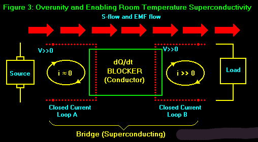
Figure 3 shows what is needed to utilize a "free-energy" source for overunity coefficient of performance of the system. First, we utilize two separate closed dq/dt-current loops. These loops are closed with respect to dq�/dt, and isolated from each other with respect to dq/dt. However, they are not necessarily closed with respect to S, dE/dt, df/dt, and emf flows, but only with respect to dq/dt.
In figure 3, the leftmost current loop (for the
source) isoptimized to produce appreciable voltage at very little
(minuscule) current dq/dt. Note that S = S(V). So this circuit produces a
powerful S-flow of energy, flowing along the conductors. Here we are
utilizing the sourcing current loop to furnish V, dE/dt, S, emf, and d/dt.
We are not using it to drive very much dq/dt. Consequently, the overall
wattage (power expended) in the sourcing loop is small.
Meanwhile, in the rightmost current loop, the
load is placed. Current dq/dt will flow in this circuit whenever V, dE/dt,
S, emf, and d�/dt are added (coupled) to it. And just like any
other "normal"dq/dt-circuit, this induced current will then kill the
dipolarity across the coupling circuit component in this "load circuit".
Notice that the coupling circuit component acts as a "source" in the load
loop.
We now introduce the concept of a "bridge". A bridge is just a dq/dt-blocked
pair of conductors (or degenerate semiconductors, or charge saturated
ferroelectric capacitors of the old "double-S" curve hysterisis loop kind,
etc). The point is, the bridge has its dq/dt-blocking component properly
placed in the sourcing circuit, so that the bridge will not pass dq/dt in
either direction, but it will pass V, dE/dt, S, emf, and also d�/dt.
The other end of the bridge is connected into a component (not shown) that
furnishes coupling. E.g., this can be a capacitor in a simple case. In the
AC case (which is best), it is ideally an LC oscillator. That LC oscillator
operating as a voltage-forced resonator is called a swinger. An LC
oscillator will oscillate whenever voltage is swung onto it properly,
whether or not any current dq/dt is furnished. An LC oscillator can be made
to furnish its own current dq/dt. An ideal way (not shown) to mount the load
, is to make the L of the oscillator the primary of a transformer, where the
load is connected across the secondary.
At any rate, ideally the bridge furnishes AC voltage to the swinger via two
dq/dt-blocked leads. The frequency of the bridge voltage is made just a wee
bit higher than the resonant frequency of the swinger. Consequently the
swinger is a voltage-driven resonator, furnishing its own dq/dt. This
"powers up" the primary of the transformer, which in turn powers up the
secondary and the load.
None of the load current dq/dt and none of the swinger current dq/dt can
pass back across the blocking bridge. Consequently the load is powered
without doing work from ramming the load current back through the back emf
of the original source.
Remember, all that the load circuit needs to "power up" is coupled potential
(emf). It does not need external current.
Note also that we have achieved room temperature superconductivity (RTSC)
across the bridge. In other words, we flowed the S across the bridge without
any divergence at all and without loss of energy to drive charged particles
as dq/dt. Consequently no energy is lost across the bridge from the sourcing
loop to the swinger/load loop.
As is well-known in Poynting theory, the J� represents the
collection and loss of a fraction of the S-flow. However, in our scheme J�
= 0 in the bridge, so there is no such energy loss in the bridge. So
energy-wise, we have pure lossless energy transport across that bridge. And
at room temperature. Without the cryogenics. So rigorously we have room
temperature conductivity.
All one needs to do is to concentrate on the energy flow, not the current J
flow, to readily accomplish room temperature superconductivity. The J�
flow is a measure of the rate of energy loss from energy transport, not the
total rate of energy transport S-flow per se.
Another advantage of doing RTSC this way is that it also enables overunity
COP at the same time. We carried all the S-flow across the bridge, not just
a small J Cooper pair portion as is done in normal RTSC. That's something
that the Cooper pairs cannot do, because they make up a very sluggish J.
The above items are some of the things that we have covered more fully in
our patent pending applications.
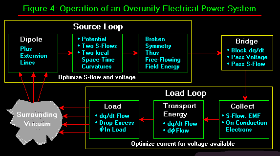
We also enclose figure 4, which is the overall electrical overunity COP
schema. Anything else that is handy, I'll just tag onto this fax also.
Feel free to put this letter plus the figures on the net if you wish.
At any rate, the work goes slowly but steadily. The Fogal semiconductor is
not yet in production, so we are also doing everything we can to assist Bill
Fogal in getting that done. We did perform a test that showed that the chip
does indeed accomplish quite anomalous noise reduction.
Also, earlier this year I finally published the exact mechanism by means of
which the Priore approach was able to cure terminal tumors, sleeping
sickness, suppressed immune systems, and clogging of the arteries in test
animals, in the 1960s to mid 1970s. [Bearden, T.E. (1995) "Vacuum Engines
and Priore's Methodology: The True Science of Energy-Medicine. Part I and
II". Explore!, 6(1), 1995, p. 66-76; 6(2), 1995, p. 50-62.] With the rising
changes in many disease agents, the bugs are becoming resistant and our
antibiotics are beginning to fail. Even the orthodox scientists are now
stating that quite bluntly. They admit that we are facing a new age of great
plagues. The Priore approach could stop cold, were it to be redeveloped.
As an interesting aside, Priore accomplished everything for his Ph.D., but
the university came under such terrible pressure from the orthodox cancer
establishment that they dared not accept his thesis. By a curious
coincidence, I happen to have in my files the actual thesis that Priore
submitted, but which was refused.
Lots of other things are also going on, but much of it cannot yet be openly
released until our patent applications are secure.
| Personally, however, I believe that the accelerated time schedule for the "New World Order"-- now set for the year 2000 -- is as a result of the imminent advent of (1) superluminal communication (we at CTEC are going to file a patent on that as well), and (2) overunity electrical energy systems. There has to be almost a police state existing in the world, if this "new electromagnetics" is to be forcibly put back under control and buried. It appears now that such a police state is imminent, both here in the U.S. and worldwide. Let us hope that the conspirators fail, and that common sense somehow resurrects and stops that nonsense. That is one reason why nets and bulletin boards are so important. It is the only way that the truth is getting through these days at all. |
So please keep up the good work; it is most important to release and
disseminate all that one can, so that the information is not lost when the
lid clamps tightly shut.
Hope things go well with you and your busy activities on the net.
Sincerely,
Tom Bearden
30 October 1995
|
Recovered through Search-Google
Legend: \text\ = italic text L_dv or L_S-tube = L subscript dv or subscript S-tube {phi} = greek letter phi =/ = different of =~ = approximately equal to ______________________________________________________________________ Fax to David Jonsson, Upsala, Sweden (internet: david@ibg.uu.se) October 30, 1995 Dear David: Confirming that I received your nice fax of Oct 6; have just been so swamped here that things have been impossible. Also received your latest fax today. Thanks for the statistics; looks as if at least a few persons are interested in this material. Will try to give you a short update. Our overunity work continues to go well, and we are making progress although severely hampered by lack of funds and laboratory equipment. (We have about a $30,000 laboratory; we need about a $150,000 lab). The best thing we have found - where the semiconductors self-target with each other at instantaneous velocity (superluminal tunneling) - requires a better lab than we possess in order to resolve the instabilities. We demonstrated such circuits two years ago that produced substantial overunity, but promptly blew themselves up because of unstability. Nonetheless, that is the wave of the future, because eventually we will do it with just a few semiconductors and ordinary switching components. But first, rigid stabilizing methods have to be worked out. We know what the problem is, and how to go about solving it, but do not have the physical technical facilities that are required. So we have turned to other overunity methods, which are beginning to look very promising. Just now we are doing much of our work on a SPICE-type simulator. It is much easier to change parameters and "blow up the simulation" than it is to blow up actual circuits. Also we have particulary made great strides in our theoretical understanding. Presently I feel that we have finally produced a legitimate theory of electrical overunity machines, and we will be publishing much of that in the future as soon as our patent application situation is completed. Simply put, there is no longer any doubt as to the precise mechanisms involved in overunity coefficient of performance. Our work in correcting electromagnetic theory also goes well, particularly with respect to my 1973 statement of the actual mechanism that generates the flow of time. That has now been extended and refined. As with other EM mechanisms, this one is also subject to direct engineering. My colleagues and I have now filed some four patents, and are in process of preparing two more. One of these is on overunity process and apparatus that we have shown to work both theoretically and by direct simulation. The other is a discovery of what appears to be a \totally\ new law of nature. This latter discovery enables energy mechanisms of such ramifications and power that one's mind is literally numbed at the prospect. It is a totally different way of addressing the energy problem. However, these patent applications we have filed are formidable documents, most running to 200 pages or more, and they have required enormous effort to write and submit. It is in these documents that we have advanced the theory of electrical overunity machines. At any rate, we are now in patent pending status on several major apparatuses and processes for electrical overunity machines, and on room temperature superconductivity (which turned out to be rather straightforward, once dq/dt-blocking is applied). One simply transfers the energy across the superconducting section as S-flow, rather than as J{Phi}. That is, one makes J=0, but in a 2-line conductor section so that d{Phi}/dt =/ 0 and S =/ 0. We have also successfully resolved the controversy that has gone on in the literature for a century with respect to the flow of energy in electrical circuits; i.e. the Poynting S-flow theory of Poynting and Heaviside. (Heaviside's version is much better than the accepted Poynting version, because it includes electrogravitation as well). As you may know, Poynting theory has not been very successfully applied to circuits of any but the simplest configurations. It is used easily and extensively, however, in systems that radiate EM energy into space. Literally, electrical engineers \do not know\ how the flow of energy is evoked from their circuits, and how it flows in their circuits. They are taught to track only the minuscule \losses and scatterings\ from that energy flow. There has been a continuing discussion (and disagreement) in the literature, and much of the material in those papers is seriously flawed, and some is downright wrong. Most EM textbooks shy away from the Poynting flow in \circuits\; Jackson, e.g., does not mention it. Most texts show a simple circuit or two, work out one or two simple examples, state that "See! This energy flow stuff works also!" and then the authors get the heck out of that "bottomless pit" with obvious relief. Of all the texts I have found, Kraus (4th edition) tries the hardest, and only contains a minor error or two. I enclose Figures 1 and 2 to show how the S-flows actually run in a simple circuit, including \from\ the vacuum and \back\ to the vacum. Interestingly, the Slepian vector J{Phi} is the energy \collected\ by the circuit \from\ the Poynting flow S. S-flow is outside the conductors and very rapid, while J is totally internal to the conductor and incredibly sluggish. When one works it all out, one finds that -- on the average -- a typical circuit collects as J{Phi} some 10E-13 of the mightly energy flow S that is evoked by the source along its conductors in the external circuit! So our modern circuitry is the most inefficient \energy collector\ imaginable. This justifies my former statement that a flashlight battery could in theory power a battleship. However, one would have to increase the \energy collection efficiency\ of the external circuit connected to the battery, quite a few times over! It would appear that there are ways of doing that; and those ways produce overunity coefficient of performance. Even so, one is still collecting only a very, very small fraction of the actual raging energy flow that the source extracts from the vacuum and send down the conductors. Here is a new one for you to ponder. It is not necessary to discover how to build a "free energy source". That is all that we have ever built anyway! Every generator and every battery is already a true, free energy source. A source does not add a single electron to the circuit; it does \not\ furnish current to the circuit. (A few very good textbooks even admit this; sources furnish potential difference, i.e. emf, nothing else). The \electrons\ for the current are furnished by the physical materials comprising the circuitry itself. E.g., on the average, there is about one free conduction electron for every atom of copper in copper wire. And so on. The Drude electron gas in the lattices of the materials furnishes the electrons for the current. If all that you draw from the dipolar source is \energy flow\, it will furnish that energy flow -- that S -- \indefinitely\. Particle physics already rigorously proves this. As is well-known in particle physics, and electric charge is a broken symmetry in the virtual photon flux of the quantum mechanical vacuum. So a dipole -- a separation of two different electrical charges -- is a double asymmetry of local spacetime. Now an asymmetry of spacetime has marvelous characteristics in particle physics. For one thing, it has to act as a source (energy flows out) or a sink (energy flows in and "disappears"). In the electrical dipole case, the energy flows out. Any dipole is a free energy source, period. \That flow will persist as long as the dipole persists. Period.\ According to the particle physics, another nice characteristics of a local asymmetry of the vaccum flux is that \something virtual has become observable\. In other words, the asymmetry is in the virtual photon flux of the local vacuum. That means that some of those \virtual\ photons have now become \observable\ photons. So our dipole furnishes observable photon flow and energy. That's rather nice, because that is just what is needed to power loads. Rigorously our electrical dipole furnishes two different flows of EM energy, one for each of the two charges, and the one greater than the other. So every electrical dipolar source we build, is \already\ a double asymmetry of ST (spacetime), and it is \already\ a source of energy flow \extracted directly from the vacuum itself\. This is really particle physics, not Tom Bearden. When you attach conductors to those separated ends of the dipole, you simply extend the charges along the conductors, so to speak. There is a Poynting flow S along both lines, from the terminals outward into the external circuit. S-flow is along an equipotential; in other words, said in another way, the nondiverging S-flows down conductors carry a standard, fixed potential V along with them. The greater the S-flow magnitude, the greater the V that is carried, and vice-versa. Along a wire, the trapped (but "dithering") electrical charges act as "railroad tracks" or "inverse waveguides" for the S-flow outside the wires and along them. Thus the S-flow does not diverge along the conductors, except for the very, very tiny fraction that enters radially into the wire and is collected as J{Phi}, and subsequently the {Phi} shaken off as a "voltage drop"in the loads, as scattered photons (heat) or as work done such as force applied to a dielectric and moved against a "giving" dielectric as mechanical strain. In the circuit, the sluggish electrons move very, very slowly as J{Phi} (an example case might be 11 feet per \hour\) down the wire, while the S-flow outside the wire is racing down the wire at essentially light speed. So the two S-flows in the circuit (one along the "positive" wire and the other along the "ground" wire) carry two different potentials, one of which we just use for reference and call "electrical ground". So the potential difference between the two S-flows is then exhibited as the potential V across the terminals, and across the two conductors. The \net\ S-flow then is a function of the magnitude of this V. The greater the V, the greater the S-flow. The two S-flows for the two ends of the dipolar source originate in the vacuum. After all, the dipole is just two asymmetries in that vacuum flux in the first place! The two S-flows then roar along the connected lines of the external circuit at light speed, flashing on out into space and beyind. Along the conductors, the potential difference {Phi} between the two S-flows also potentializes the sluggish electrons to J{Phi}, but the J (and consequently the J{Phi}) moves only at the \electron drift velocity\. During one second of flow, the S-flow fills an "equivalent tube" in space with energy; a tube that is about 300,000,000 meters long! Meanwhile, the sluggish electrons making up the collected fraction J{Phi} of that energy, have "drifted" a distance down the wire that is less than the thickness of one's fingernail. Since the {Phi} of the J{Phi} tube is the same as the {Phi} of the S-tube, then the fraction k of energy collected in that one second as J{Phi}, is just the ratio of the lengths of movement for J{Phi} vs S. So this gives k = [L_dv] / [L_S-tube] =~ 10E-13. In a given situation this fraction will of course vary a little, but that's a rough ballpark figure. It serves to illustrate the gross inefficiency of energy collection performed by our normal circuits. Now one can see why all sources are already free energy sources. The potentialized electrons, travelling as J{Phi}, undergo increased collisions in the loads, resulting in shaking off their excess {Phi}, (in a resistor, e.g., the {Phi} is shaken off the J{Phi} as scattered photons, which is heat). Notice that none of that load work has anything at all to do with depletion of the source's ability to furnish emf and V and S. So long as the source's separation of charges is okay, the emf, V, and S will continue to be furnished unabeated, because these are being "pumped" by the double local asymmetry of the local vacuum's virtual photon flux exchange with the separated dipolar charges! Notice that we have combined particle physics, general relativity, classical electrodynamics, and quantum electrodynamics. This is a really unified field theory approach. At any rate, we already have jillions of free energy electrical power \sources\. We have never had anything else. The reason that we do not have free energy \systems\, is because the engineers deliberately ram those spent electrons back through the ground return line, and through the back emf of the source. This means that one-half the tiny fraction of S-energy that is collected as J{Phi}, is expended as work to drive the electrons back though the source against its back emf so as to potentialize those electrons again to J{Phi}. This "ramming"does work inside the source. Specifically, it does work upon the sources' separated charges, gradually destroying that separation and hence the source's dipolarity. That of course destroys the source's ability to furnish emf, V, and S. Figure 3 shows what is needed to utilize a "free-energy" source for overunity coefficient of performance of the \system\. First, we utilize two separate closed dq/dt-current loops. These loops are closed with respect to dq/dt, and isolated from each other with respect to dq/dt. However, they are not necessarily closed with respect to S, dE/dt, df/dt, and emf flows, but only with respect to dq/dt. In figure 3, the leftmost current loop (for the source) isoptimized to produce appreciable voltage at very little (minuscule) current dq/dt. Note that S = S(V). So this circuit produces a powerful S-flow of energy, flowing along the conductors. Here we are utilizing the sourcing current loop to furnish V, dE/dt, S, emf, and d{Phi}/dt. We are not using it to drive very much dq/dt. Consequently, the overall wattage (power expended) in the sourcing loop is small. Meanwhile, in the rightmost current loop, the load is placed. Current dq/dt will flow in this circuit whenever V, dE/dt, S, emf, and d{Phi}/dt are added (coupled) to it. And just like any other "normal"dq/dt-circuit, this induced current will then kill the dipolarity across the \coupling circuit component\ in this "load circuit". Notice that the coupling circuit component acts as a "source" in the load loop. We now introduce the concept of a "bridge". A bridge is just a dq/dt-blocked pair of conductors (or degenerate semiconductors, or charge saturated ferroelectric capacitors of the old "double-S" curve hysterisis loop kind, etc). The point is, the bridge has its dq/dt-blocking component properly placed in the sourcing circuit, so that the bridge will not pass dq/dt in either direction, but it will pass V, dE/dt, S, emf, and also d{Phi}/dt. The other end of the bridge is connected into a component (not shown) that furnishes coupling. E.g., this can be a capacitor in a simple case. In the AC case (which is best), it is ideally an LC oscillator. That LC oscillator operating as a voltage-forced resonator is called a \swinger\. An LC oscillator will oscillate whenever voltage is swung onto it properly, whether or not any current dq/dt is furnished. An LC oscillator can be made to furnish its own current dq/dt. An ideal way (not shown) to mount the load , is to make the L of the oscillator the primary of a transformer, where the load is connected across the secondary. At any rate, ideally the bridge furnishes AC voltage to the swinger via two dq/dt-blocked leads. The frequency of the bridge voltage is made just a wee bit higher than the resonant frequency of the swinger. Consequently the swinger is a voltage-driven resonator, furnishing its own dq/dt. This "powers up" the primary of the transformer, which in turn powers up the secondary and the load. None of the load current dq/dt and none of the swinger current dq/dt can pass back across the blocking bridge. Consequently the load is powered without doing work from ramming the load current back through the back emf of the original source. Remember, all that the load circuit needs to "power up" is coupled potential (emf). It does \not\ need external current. Note also that we have achieved room temperature superconductivity (RTSC) across the bridge. In other words, we flowed the S across the bridge without any divergence at all and without loss of energy to drive charged particles as dq/dt. Consequently no energy is lost across the bridge from the sourcing loop to the swinger/load loop. As is well-known in Poynting theory, the J{Phi} represents the collection and loss of a fraction of the S-flow. However, in our scheme J{Phi} = 0 in the bridge, so there is no such energy loss in the bridge. So \energy\-wise, we have pure lossless energy transport across that bridge. And at room temperature. Without the cryogenics. So rigorously we have \room temperature conductivity\. All one needs to do is to concentrate on the \energy\ flow, not the current J{Phi} flow, to readily accomplish room temperature superconductivity. The J{Phi} flow is a measure of the rate of energy \loss\ from energy transport, not the total rate of energy transport S-flow per se. Another advantage of doing RTSC this way is that it also enables overunity COP at the same time. We carried \all\ the S-flow across the bridge, not just a small J{Phi} Cooper pair portion as is done in normal RTSC. That's something that the Cooper pairs cannot do, because they make up a very sluggish J{Phi}. The above items are some of the things that we have covered more fully in our patent pending applications. We also inclose figure 4, which is the overall electrical overunity COP schema. Anything else that is handy, I'll just tag onto this fax also. Feel free to put this letter plus the figures on the net if you wish. At any rate, the work goes slowly but steadily. The Fogal semiconductor is not yet in production, so we are also doing everything we can to assist Bill Fogal in getting that done. We did perform a test that showed that the chip does indeed accomplish quite anomalous noise reduction. Also, earlier this year I finally published the exact mechanism by means of which the Priore approach was able to cure terminal tumors, sleeping sickness, suppressed immune systems, and clogging of the arteries in test animals, in the 1960s to mid 1970s. [Bearden, T.E. (1995) "Vacuum Engines and Priore's Methodology: The True Science of Energy-Medicine. Part I and II". Explore!, 6(1), 1995, p. 66-76; 6(2), 1995, p. 50-62.] With the rising changes in many disease agents, the bugs are becoming resistant and our antibiotics are beginning to fail. Even the orthodox scientists are now stating that quite bluntly. They admit that we are facing a new age of great plagues. The Priore approach could stop cold, were it to be redeveloped. As an interesting aside, Priore accomplished everything for his Ph.D., but the university came under such terrible pressure from the orthodox cancer establishment that they dared not accept his thesis. By a curious coincidence, I happen to have in my files the actual thesis that Priore submitted, but which was refused. Lots of other things are also going on, but much of it cannot yet be openly released until our patent applications are secure. Personally, however, I believe that the accelerated time schedule for the "New World Order"-- now set for the year 2000 -- is as a result of the imminent advent of (1) superluminal communication (we at CTEC are going to file a patent on that as well), and (2) overunity electrical energy systems. There has to be almost a police state existing in the world, if this "new electromagnetics" is to be forcibly put back under control and buried. It appears now that such a police state is imminent, both here in the U.S. and worldwide. Let us hope that the conspirators fail, and that common sense somehow resurrects and stops that nonsense. That is one reason why nets and bulletin boards are so important. It is the only way that the truth is getting through these days at all. So please keep up the good work; it is most important to release and disseminate all that one can, so that the information is not lost when the lid clamps tightly shut. Hope things go well with you and your busy activitie on the net. Sincerely, Tom Bearden 30 October 1995 Incls Figs (a/s) Other as available |