|
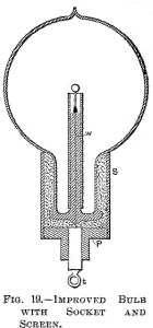
It is of advantage to make the tube t very thick, the hole through it very small, and to blow the sphere s very thin. It is of the greatest importance that the sphere s be placed in the centre of the globe L.
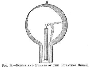
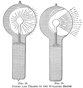
Figs. 14, 15 and 16 indicate different forms, or stages, of the
brush. Fig. 14 shows the brush as it first appears in a bulb
provided with a conducting terminal; but, as in such a bulb it very
soon disappears—often after a few minutes—I will confine myself to
the description of the phenomenon as seen in a bulb without
conducting electrode. It is observed under the following conditions:
Shortly afterward one may notice that
the luminosity is unevenly distributed in the globe, and after
passing the current for some time the bulb appears as in Fig. 15.
From this stage the phenomenon will gradually pass to that indicated
in Fig. 16, after some minutes, hours, days or weeks, according as
the bulb is worked. Warming the bulb or increasing the potential
hastens the transit.
It may begin to spin around the terminal long before it reaches that sensitive stage. When it begins to turn around principally, but also before, it is affected by a magnet, and at a certain stage it is susceptible to magnetic influence to an astonishing degree. A small permanent magnet, with its poles at a distance of no more than two centimeters, will affect it visibly at a distance of two meters, slowing down or accelerating the rotation according to how it is held relatively to the brush.
I think I have
observed that at the stage when it is most sensitive to magnetic, it
is not most sensitive to electrostatic, influence. My explanation
is, that the electrostatic attraction between the brush and the
glass of the bulb, which retards the rotation, grows much quicker
than the magnetic influence when the intensity of the stream is
increased.
The rotation can be slowed down or accelerated by the approach or receding of the observer, or any conducting body, but it cannot be reversed by putting the bulb in any position. When it is in the state of the highest sensitiveness and the potential or frequency be varied the sensitiveness is rapidly diminished. Changing either of these but little will generally stop the rotation.
The sensitiveness is likewise affected by the variations
of temperature. To attain great sensitiveness it is necessary to
have the small sphere s in the centre of the globe L, as otherwise
the electrostatic action of the glass of the globe will tend to stop
the rotation. The sphere s should be small and of uniform thickness;
any dissymmetry of course has the effect to diminish the
sensitiveness.
That the formation of the stream is due to an irregularity is apparent from the fact that it has the tendency to remain in one position, and rotation occurs most generally only when it is brought out of this position by electrostatic or magnetic influence. When in an extremely sensitive state it rests in one position, most curious experiments may be performed with it.
For instance, the experimenter may, by selecting
a proper position, approach the hand at a certain considerable
distance to the bulb, and he may cause the brush to pass off by
merely stiffening the muscles of the arm. When it begins to rotate
slowly, and the hands are held at a proper distance, it is
impossible to make even the slightest motion without producing a
visible effect upon the brush. A metal plate connected to the other
terminal of the coil affects it at a great distance, slowing down
the rotation often to one turn a second.
The
experimenter may bring his body in contact with the terminals of the
secondary of the coil, or attach to one or both terminals insulated
bodies of very small bulk, such as bulbs, and he may produce a
considerable rise or fall of potential, and greatly affect the flow
of the current through the primary. In the experiment before shown,
in which a brush appears at a wire attached to one terminal, and the
wire is vibrated when the experimenter brings his insulated body in
contact with the other terminal of the coil, the sudden rise of
potential was made evident.
But if one of the opposing surfaces is screened, or if, generally
speaking, the bombardment on this side is weakened in some way or
other, there remains the repulsion exerted upon the other, and the
fan is set in rotation. The screening is best effected by fastening
upon one of the opposing sides of the fan insulated conducting
coatings, or, if the fan is made in the shape of an ordinary
propeller screw, by fastening on one side, and close to it, an
insulated metal plate. The static screen may, however, be omitted,
and simply a thickness of insulating material fastened to one of the
sides of the fan.
Now, it is
very easy to adjust the conditions so that the potential is normally
not sufficient to turn the fan, but that by connecting the other
terminal of the coil with an insulated body it rises to a much
greater value, so as to rotate the fan, and it is likewise possible
to stop the rotation by connecting to the terminal a body of
different size, thereby diminishing the potential.
In such case, of course, if
there is any repulsion at all of the molecules from the vanes, it
must be very small. It is possible, however, that the result is in
part due to the fact that the greater part of the discharge passes
from the leading-in wire through the highly conducting gas, instead
of passing off from the conducting vanes.
The iron core is
employed for obvious reasons, but it is not essential to the
operation. To improve the motor, the iron core is made to encircle
the armature. Again to improve, the secondary coil is made to
overlap partly the primary, so that it cannot free itself from a
strong inductive action of the latter, repel its lines as it may.
Once more to improve, the proper difference of phase is obtained
between the primary and secondary currents by a condenser,
self-induction, resistance or equivalent windings.
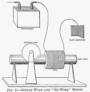
It is of some interest, in conjunction with the historical Arago experiment, to mention that in lag or phase motors I have produced rotation in the opposite direction to the moving field, which means that in that experiment the magnet may not rotate, or may even rotate in the opposite direction to the moving disc. Here, then, is a motor (diagrammatically illustrated in Fig. 17), comprising a coil and iron core, and a freely movable copper disc in proximity to the latter. To demonstrate a novel and interesting feature, I have, for a reason which I will explain, selected this type of motor. When the ends of the coil are connected to the terminals of an alternator the disc is set in rotation. But it is not this experiment, now well known, which I desire to perform. What I wish to show you is that this motor rotates with one single connection between it and the generator; that is to say, one terminal of the motor is connected to one terminal of the generator—in this case the secondary of a high-tension induction coil—the other terminals of motor and generator being insulated in space.
To produce rotation it is generally (but not absolutely) necessary to connect the free end of the motor coil to an insulated body of some size. The experimenter's body is more than sufficient. If he touches the free terminal with an object held in the hand, a current passes through the coil and the copper disc is set in rotation. If an exhausted tube is put in series with the coil, the tube lights brilliantly, showing the passage of a strong current. Instead of the experimenter's body, a small metal sheet suspended on a cord may be used with the same result.
In this case the plate acts as a condenser in series with the coil. It counteracts the self-induction of the latter and allows a strong current to pass. In such a combination, the greater the self-induction of the coil the smaller need be the plate, and this means that a lower frequency, or eventually a lower potential, is required to operate the motor. A single coil wound upon a core has a high self-induction; for this reason principally, this type of motor was chosen to perform the experiment.
Were a secondary closed coil
wound upon the core, it would tend to diminish the self-induction,
and then it would be necessary to employ a much higher frequency and
potential. Neither would be advisable, for a higher potential would
endanger the insulation of the small primary coil, and a higher
frequency would result in a materially diminished torque.
There is no doubt that with the enormous potentials obtainable by the use of high frequencies and oil insulation luminous discharges might be passed through many miles of rarefied air, and that, by thus directing the energy of many hundreds or thousands of horse-power, motors or lamps might be operated at considerable distances from stationary sources. But such schemes are mentioned merely as possibilities. We shall have no need to transmit power in this way. We shall have no need to transmit power at all.
Ere many generations pass, our machinery will be driven by a power obtainable at any point of the universe. This idea is not novel. Men have been led to it long ago by instinct or reason. It has been expressed in many ways, and in many places, in the history of old and new. We find it in the delightful myth of Antheus, who derives power from the earth; we find it among the subtle speculations of one of your splendid mathematicians, and in many hints and statements of thinkers of the present time. Throughout space there is energy. Is this energy static or kinetic?
If static our hopes are in vain; if kinetic—and
this we know it is, for certain—then it is a mere question of time
when men will succeed in attaching their machinery to the very
wheelwork of nature. Of all, living or dead, Crookes came nearest to
doing it. His radiometer will turn in the light of day and in the
darkness of the night; it will turn everywhere where there is heat,
and heat is everywhere. But, unfortunately, this beautiful little
machine, while it goes down to posterity as the most interesting,
must likewise be put on record as the most inefficient machine ever
invented!
On each glass stem in the inside of the bulb was slipped a highly polished tube made of aluminium sheet, which fitted the stem and was held on it by spring pressure. The function of this aluminium tube will be explained subsequently. In each bulb an equal length of filament protruded above the metal tube. It is sufficient to say now that under these conditions equal lengths of filament of the same thickness—in other words, bodies of equal bulk—were brought to incandescence. The three bulbs were sealed to a glass tube, which was connected to a Sprengel pump. When a high vacuum had been reached, the glass tube carrying the bulbs was sealed off.
A current was then turned on successively on each bulb, and it was found that the filaments came to about the same brightness, and, if anything, the smallest bulb, which was placed midway between the two larger ones, may have been slightly brighter. This result was expected, for when either of the bulbs was connected to the coil the luminosity spread through the other two, hence the three bulbs constituted really one vessel. When all the three bulbs were connected in multiple arc to the coil, in the largest of them the filament glowed brightest, in the next smaller it was a little less bright, and in the smallest it only came to redness.
The bulbs were then sealed off and separately tried. The
brightness of the filaments was now such as would have been expected
on the supposition that the energy given off was proportionate to
the surface of the bulb, this surface in each case representing one
of the coatings of a condenser. Accordingly, time was less
difference between the largest and the middle sized than between the
latter and the smallest bulb.
This observation led me to exchange
the position of the bulbs, and I then observed that whichever of the
bulbs was in the middle it was by far less bright than it was in any
other position. This mystifying result was, of course, found to be
due to the electrostatic action between the bulbs. When they were
placed at a considerable distance, or when they were attached to the
corners of an equilateral triangle of copper wire, they glowed about
in the order determined by their surfaces.
This object is best attained in the spherical bulb; but it is also attained in a cylindrical vessel with one or two straight filaments coinciding with its axis, and possibly also in parabolical or spherical bulbs with the refractory body or bodies placed in the focus or foci of the same; though the latter is not probable, as the electrified atoms should in all cases rebound normally from the surface they strike, unless the speed were excessive, in which case they would probably follow the general law of reflection.
No matter
what shape the vessel may have, if the exhaustion be low, a filament
mounted in the globe is brought to the same degree of incandescence
in all parts; but if the exhaustion be high and the bulb be
spherical or pear-shaped, as usual, focal points form and the
filament is heated to a higher degree at or near such points.
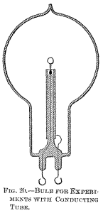
To obviate this loss, or at least to reduce it to a minimum, I usually screen the rarefied gas surrounding the stem from the inductive action of the leading-in wire by providing the stem with a tube or coating of conducting material. It seems beyond doubt that the best among metals to employ for this purpose is aluminium, on account of its many remarkable properties. Its only fault is that it is easily fusible, and, therefore, its distance from the incandescing body should be properly estimated. Usually, a thin tube, of a diameter somewhat smaller than that of the glass stem, is made of the finest aluminium sheet, and slipped on the stem.
The tube is conveniently prepared by wrapping around a rod fastened in a lathe a piece of aluminium sheet of the proper size, grasping the sheet firmly with clean chamois leather or blotting paper, and spinning the rod very fast. The sheet is wound tightly around the rod, and a highly polished tube of one or three layers of the sheet is obtained. When slipped on the stem, the pressure is generally sufficient to prevent it from slipping off, but, for safety, the lower edge of the sheet may be turned inside.
The upper inside corner of the sheet—that is, the one which is nearest to the refractory incandescent body—should be cut out diagonally, as it often happens that, in consequence of the intense heat, this corner turns toward the inside and comes very near to, or in contact with, the wire, or filament, supporting the refractory body. The greater part of the energy supplied to the bulb is then used up in heating the metal tube, and the bulb is rendered useless for the purpose.
The aluminium sheet should project above the glass stem more or less—one inch or so—or else, if the glass be too close to the incandescing body, it may be strongly heated and become more or less conducting, whereupon it may be ruptured, or may, by its conductivity, establish a good electrical connection between the metal tube and the leading-in wire, in which case, again, most of the energy will be lost in heating the former.
Perhaps the best way
is to make the top of the glass tube, for about an inch, of a much
smaller diameter. To still further reduce the danger arising from
the heating of the glass stem, and also with the view of preventing
an electrical connection between the metal tube and the electrode, I
preferably wrap the stem with several layers of thin mica, which
extends at least as far as the metal tube. In some bulbs I have also
used an outside insulating cover.
When they are separately connected to the coil giving a certain potential, the carbon filament in the bulb provided with the aluminium screen is rendered highly incandescent, while the filament in the other bulb may, with the same potential, not even come to redness, although in reality the latter bulb takes generally more energy than the former. When they are both connected together to the terminal, the difference is even more apparent, showing the importance of the screening.
The metal tube placed on the stem containing the leading-in wire performs really two distinct functions: First: it acts more or less as an electrostatic screen, thus economizing the energy supplied to the bulb; and, second, to whatever extent it may fail to act electrostatically, it acts mechanically, preventing the bombardment, and consequently intense heating and possible deterioration of the slender support of the refractory incandescent body, or of the glass stem containing the leading-in wire.
I say slender support, for it is evident that in
order to confine the heat more completely to the incandescing body
its support should be very thin, so as to carry away the smallest
possible amount of heat by conduction. Of all the supports used I
have found an ordinary incandescent lamp filament to be the best,
principally because among conductors it can withstand the highest
degrees of heat.
As long as the
electrical connection is not good, the conducting tube is always of
some advantage, for although it may not greatly economize energy,
still it protects the support of the refractory button, and is a
means for concentrating more energy upon the same.
But this must diminish the energy lost in the bombardment for two reasons: first, the charge given up by the atoms spreads over a great area, and hence the electric density at any point is small, and the atoms are repelled with less energy than they would be if they would strike against a good insulator: secondly, as the tube is electrified by the atoms which first come in contact with it, the progress of the following atoms against the tube is more or less checked by the repulsion which the electrified tube must exert upon the similarly electrified atoms.
This repulsion may perhaps be
sufficient to prevent a large portion of the atoms from striking the
tube, but at any rate it must diminish the energy of their impact.
It is clear that when the exhaustion is very low, and the rarefied
gas well conducting, neither of the above effects can occur, and, on
the other hand, the fewer the atoms, with the greater freedom they
move; in other words, the higher the degree of exhaustion, up to a
limit, the more telling will be both the effects.
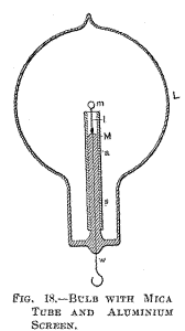
Fig. 18 is a section through a spherical bulb L, with the glass stem
s, containing the leading-in wire w; which has a lamp filament l
fastened to it, serving to support the refractory button m in the
centre. M is a sheet of thin mica wound in several layers around the
stem s, and a is the aluminium tube.
This terminal must be
well insulated from the metal tube S, therefore, if the cement used
is conducting—and most generally it is sufficiently so—the space
between the plug P and the neck of the bulb should be filled with
some good insulating material, as mica powder. Since the bombardment against the stem containing the leading-in wire is due to the inductive action of the latter upon the rarefied gas, it is of advantage to reduce this action as far as practicable by employing a very thin wire, surrounded by a very thick insulation of glass or other material, and by making the wire passing through the rarefied gas as short as practicable.
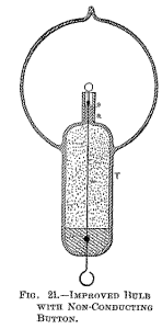
To combine these features I employ a large tube T (Fig. 21), which protrudes into the bulb to some distance, and carries on the top a very short glass stem s, into which is sealed the leading-in wire w, and I protect the top of the glass stem against the heat by a small, aluminium tube a and a layer of mica underneath the same, as usual. The wire w, passing through the large tube to the outside of the bulb, should be well insulated—with a glass tube, for instance—and the space between ought to be filled out with some excellent insulator. Among many insulating powders I have tried, I have found that mica powder is the best to employ. If this precaution is not taken, the tube T, protruding into the bulb, will surely be cracked in consequence of the heating by the brushes which are apt to form in the upper part of the tube, near the exhausted globe, especially if the vacuum be excellent, and therefore the potential necessary to operate the lamp very high.
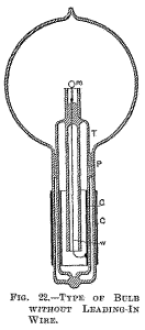
Fig. 22 illustrates a similar arrangement, with a large tube T protruding in to the part of the bulb containing the refractors button m. In this case the wire leading from the outside into the bulb is omitted, the energy required being supplied through condenser coatings C C.
The insulating packing P should in this construction be tightly fitting to the glass, and rather wide, or otherwise the discharge might avoid passing through the wire w, which connects the inside condenser coating to the incandescent button m. The molecular bombardment against the glass stem in the bulb is a source of great trouble. As illustration I will cite a phenomenon only too frequently and unwillingly observed.
A bulb,
preferably a large one, may be taken, and a good conducting body,
such as a piece of carbon, may be mounted in it upon a platinum wire
sealed in the glass stem. The bulb may be exhausted to a fairly high
degree, nearly to the point when phosphorescence begins to appear. When the bulb is connected with the coil, the piece of carbon, if small, may become highly incandescent at first, but its brightness immediately diminishes, and then the discharge may break through the glass somewhere in the middle of the stem, in the form of bright sparks, in spite of the fact that the platinum wire is in good electrical connection with the rarefied gas through the piece of carbon or metal at the top. The first sparks are singularly bright, recalling those drawn from a clear surface of mercury.
But, as they heat the glass rapidly, they, of course, lose their brightness, and cease when the glass at the ruptured place becomes incandescent, or generally sufficiently hot to conduct. When observed for the first time the phenomenon must appear very curious, and shows in a striking manner how radically different alternate currents, or impulses, of high frequency behave, as compared with steady currents, or currents of low frequency.
With such currents—namely, the latter—the phenomenon would of course not occur. When frequencies such as are obtained by mechanical means are used, I think that the rupture of the glass is more or less the consequence of the bombardment, which warms it up and impairs its insulating power; but with frequencies obtainable with condensers I have no doubt that the glass may give way without previous heating.
Although this appears most singular at first, it is in reality what we might expect to occur. The energy supplied to the wire leading into the bulb is given off partly by direct action through the carbon button, and partly by inductive action through the glass surrounding the wire. The case is thus analogous to that in which a condenser shunted by a conductor of low resistance is connected to a source of alternating currents.
As long as the frequencies are low, the
conductor gets the most, and the condenser is perfectly safe: but
when the frequency becomes excessive, the role of the conductor may
become quite insignificant. In the latter case the difference of
potential at the terminals of the condenser may become so great as
to rupture the dielectric, notwithstanding the fact that the
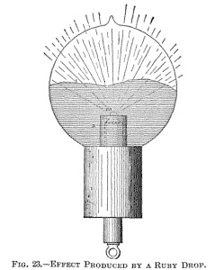
terminals are joined by a conductor of low resistance. A different arrangement used in some of the bulbs constructed is illustrated in Fig. 23. In this instance a non-conductor m is mounted in a piece of common arc light carbon so as to project some small distance above the latter. The carbon piece is connected to the leading-in wire passing through a glass stem, which is wrapped with several layers of mica. An aluminium tube a is employed as usual for screening.
It is so arranged that it reaches very nearly
as high as the carbon and only the non-conductor m projects a little
above it. The bombardment goes at first against the upper surface of
carbon, the lower parts being protected by the aluminium tube. As
soon, however, as the non-conductor m is heated it is rendered good
conducting, and then it becomes the centre of the bombardment, being
most exposed to the same.
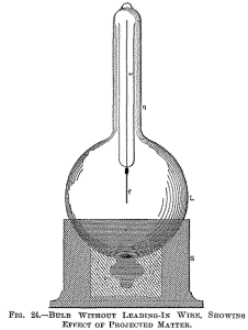
A fine
lamp filament f, supported on a wire w, passes through the centre of
the globe L. The filament is rendered incandescent in the middle
portion, where the bombardment proceeding from the lower inside
surface of the globe is most intense. The lower portion of the
globe, as far as the socket S reaches, is rendered conducting,
either by a tinfoil coating or otherwise, and the external electrode
is connected to a terminal of the coil.
The observation made was in accordance with generally
accepted notions. In a highly exhausted bulb electricity is carried
off from the electrode by independent carriers, which are partly the
atoms, or molecules, of the residual atmosphere, and partly the
atoms, molecules, or lumps thrown off from the electrode. If the
electrode is composed of bodies of different character, and if one
of these is more easily disintegrated than the others, most of the
electricity supplied is carried off from that body, which is then
brought to a higher temperature than the others, and this the more,
as upon an increase of the temperature the body is still more easily
disintegrated.
It is now possible that in consequence of the violent disintegration the spot attacked sinks in temperature, or that a counter force is created, as in an arc; at any rate, the local tearing off meets with the limitations incident to the experiment, whereupon the same process occurs on another place. To the eye the electrode appears uniformly brilliant, but there are upon it points constantly shifting and wandering around, of a temperature far above the mean, and this materially hastens the process of deterioration.
That some such thing occurs, at least when the electrode is at a lower temperature, sufficient experimental evidence can be obtained in the following manner: Exhaust a bulb to a very high degree, so that with a fairly high potential the discharge cannot pass—that is, not a luminous one, for a weak invisible discharge occurs always, in all probability. Now raise slowly and carefully the potential, leaving the primary current on no more than for an instant.
At a certain point, two,
three, or half a dozen phosphorescent spots will appear on the
globe. These places of the glass are evidently more violently
bombarded than others, this being due to the unevenly distributed
electric density, necessitated, of course, by sharp projections, or,
generally speaking, irregularities of the electrode. But the
luminous patches are constantly changing in position, which is
especially well observable if one manages to produce very few, and
this indicates that the configuration of the electrode is rapidly
changing.
We cannot go very far with a blast, nor by confining heat in a furnace, but in an exhausted bulb we can concentrate any amount of energy upon a minute button. Leaving practicability out of consideration, this, then, would be the means which, in my opinion, would enable us to reach the highest temperature. But a great difficulty when proceeding in this way is encountered, namely, in most cases the body is carried off before it can fuse and form a drop.
This difficulty exists principally with an oxide such as zirconia, because it cannot be compressed in so hard a cake that it would not be carried off quickly. I endeavored repeatedly to fuse zirconia, placing it in a cup or arc light carbon as indicated in Fig. 23. It glowed with a most intense light, and the stream of the particles projected out of the carbon cup was of a vivid white: but whether it was compressed in a cake or made into a paste with carbon, it was carried off before it could be fused.
The carbon cup containing the zirconia had
to be mounted very low in the neck of a large bulb, as the heating
of the glass by the projected particles of the oxide was so rapid
that in the first trial the bulb was cracked almost in an instant
when the current was turned on. The heating of the glass by the
projected particles was found to be always greater when the carbon
cup contained a body which was rapidly carried off—I presume because
in such cases, with the same potential, higher speeds were reached,
and also because, per unit of time, more matter was projected—that
is, more particles would strike the glass.
In this manner an intensely phosphorescent, sharply
defined line, l, corresponding to the outline of the drop, is
produced, which spreads slowly over the globe as the drop gets
larger. When the mass begins to boil, small bubbles and cavities are
formed, which cause dark colored spots to sweep across the globe.
The bulb may be turned downward without fear of the drop falling
off, as the mass possesses considerable viscosity.
A small piece of pumice stone was stuck on a platinum wire, and first melted to it in a gas burner. The wire was next placed between two pieces of charcoal and a burner applied so as to produce an intense heat, sufficient to melt down the pumice stone into a small glass-like button. The platinum wire had to be taken of sufficient thickness to prevent its melting in the fire. While in the charcoal fire, or when held in a burner to get a better idea of the degree of heat, the button glowed with great brilliancy.
The wire with the button was
then mounted in a bulb, and upon exhausting the same to a high
degree, the current was turned on slowly so as to prevent the
cracking of the button. The button was heated to the point of
fusion, and when it melted it did not, apparently, glow with the
same brilliancy as before, and this would indicate a lower
temperature. Leaving out of consideration the observer's possible,
and even probable, error, the question is, can a body under these
conditions be brought from a solid to a liquid state with evolution
of less light?
Next, suppose we diminish to any degree we choose the energy steadily supplied, and, instead, supply energy which rises and falls according to a certain law. Now, when the drop is formed, there will be emitted from it three different kinds of vibrations—the ordinary visible, and two kinds of invisible waves: that is, the ordinary dark waves of all lengths, and, in addition, waves of a well defined character. The latter would not exist by a steady supply of the energy; still they help to jar and loosen the structure. If this really be the case, then the ruby drop will emit relatively less visible and more invisible waves than before.
Thus it would seem that when a platinum wire, for instance, is fused by currents alternating with extreme rapidity, it emits at the point of fusion less light and more invisible radiation than it does when melted by a steady current, though the total energy used up in the process of fusion is the same in both cases. Or, to cite another example, a lamp filament is not capable of withstanding as long with currents of extreme frequency as it does with steady currents, assuming that it be worked at the same luminous intensity.
This means that for rapidly alternating currents the filament should be shorter and thicker. The higher the frequency—that is, the greater the departure from the steady flow—the worse it would be for the filament. But if the truth of this remark were demonstrated, it would be erroneous to conclude that such a refractory button as used in these bulbs would be deteriorated quicker by currents of extremely high frequency than by steady or low frequency currents. From experience I may say that just the opposite holds good: the button withstands the bombardment better with currents of very high frequency.
But this is due to the fact that a high frequency
discharge passes through a rarefied gas with much greater freedom
than a steady or low frequency discharge, and this will say that
with the former we can work with a lower potential or with a less
violent impact. As long, then, as the gas is of no consequence, a
steady or low frequency current is better; but as soon as the action
of the gas is desired and important, high frequencies are
preferable.
From many experiences I conclude that lamp filaments obtained in this manner can be advantageously used only with low potentials and low frequency currents. Some kinds of carbon withstand so well that, in order to bring them to the point of fusion, it is necessary to employ very small buttons. In this case the observation is rendered very difficult on account of the intense heat produced.
Nevertheless there can be no doubt that
all kinds of carbon are fused under the molecular bombardment, but
the liquid state must be one of great instability. Of all the bodies
tried there were two which withstood best—diamond and carborundum.
These two showed up about equally, but the latter was preferable,
for many reasons. As it is more than likely that this body is not
yet generally known, I will venture to call your attention to it.
The majority were opaque, but there were some which were transparent and colored. The crystals are a kind of carbon containing some impurities; they are extremely hard, and withstand for a long time even an oxygen blast. When the blast is directed against them they at first form a cake of some compactness, probably in consequence of the fusion of impurities they contain.
The mass withstands for a very long time the blast without further
fusion; but a slow carrying off, or burning, occurs, and, finally, a
small quantity of a glass-like residue is left, which, I suppose, is
melted alumina. When compressed strongly they conduct very well, but
not as well as ordinary carbon. The powder, which is obtained from
the crystals in some way, is practically non-conducting. It affords
a magnificent polishing material for stones.
The only difficulty which I have found in its use in
connection with these experiments was to find some binding material
which would resist the heat and the effect of the bombardment as
successfully as carborundum itself does.
The tar softens and forms a drop on the point of the filament, the crystals adhering to the surface of the drop. By regulating the distance from the plate the tar is slowly dried out and the button becomes solid. I then once more dip the button in tar and hold it again over a plate until the tar is evaporated, leaving only a hard mass which firmly binds the crystals. When a larger button is required I repeat the process several times, and I generally also cover the filament a certain distance below the button with crystals.
The button being
mounted in a bulb, when a good vacuum has been reached, first a weak
and then a strong discharge is passed through the bulb to carbonize
the tar and expel all gases, and later it is brought to a very
intense incandescence.
As it does not seem to blacken the globe in the least, it might be found useful for coating the filaments of ordinary incandescent lamps, and I think that it is even possible to produce thin threads or sticks of carborundum which will replace the ordinary filaments in an incandescent lamp. A carborundum coating seems to be more durable than other coatings, not only because the carborundum can withstand high degrees of heat, but also because it seems to unite with the carbon better than any other material I have tried.
A coating of zirconia or any other oxide, for instance, is far more quickly
destroyed. I prepared buttons of diamond dust in the same manner as
of carborundum, and these came in durability nearest to those
prepared of carborundum, but the binding paste gave way much more
quickly in the diamond buttons: this, however, I attributed to the
size and irregularity of the grains of the diamond.
Therefore it is
quite possible that at some extremely high frequency, when behaving
practically as a non-conductor, a metal or any other conductor might
exhibit the quality of phosphorescence, even though it be entirely
incapable of phosphorescing under the impact of a low-frequency
discharge. There is, however, another possible way how a conductor
might at least appear to phosphoresce.
Now such a result, theoretically at least, is possible, for it is a mere question of potential or speed. Assume the potential of the electrode, and consequently the speed of the projected atoms, to be sufficiently high, the surface of the metal piece against which the atoms are projected would be rendered highly incandescent, since the process of heat generation would be incomparably faster than that of radiating or conducting away from the surface of the collision. In the eye of the observer a single impact of the atoms would cause an instantaneous flash, but if the impacts were repeated with sufficient rapidity they would produce a continuous impression upon his retina.
To him then the surface of the metal would appear continuously incandescent and of constant luminous intensity, while in reality the light would be either intermittent or at least changing periodically in intensity. The metal piece would rise in temperature until equilibrium was attained—that is until the energy continuously radiated would equal that intermittently supplied. But the supplied energy might under such conditions not be sufficient to bring the body to any more than a very moderate mean temperature, especially if the frequency of the atomic impacts be very low—just enough that the fluctuation of the intensity of the light emitted could not be detected by the eye.
The body would now, owing to the
manner in which the energy is supplied, emit a strong light, and yet
be at a comparatively very low mean temperature. How could the
observer call the luminosity thus produced? Even if the analysis of
the light would teach him something definite, still he would
probably rank it under the phenomena of phosphorescence. It is
conceivable that in such a way both conducting and non-conducting
bodies may be maintained at a certain luminous intensity, but the
energy required would very greatly vary with the nature and
properties of the bodies.
When the metal disc is covered
with carborundum crystals, the film is far more intense, and
snow-white. This I found later to be merely an effect of the bright
surface of the crystals, for when an aluminium electrode was highly
polished it exhibited more or less the same phenomenon. I made a
number of experiments with the samples of crystals obtained,
principally because it would have been of special interest to find
that they are capable of phosphorescence, on account of their being
conducting. I could not produce phosphorescence distinctly, but I
must remark that a decisive opinion cannot be formed until other
experimenters have gone over the same ground.
The higher the incandescence,
the quicker the mean vibration, the greater is the economy of the
light production. But to maintain a mass of gas at a high degree of
incandescence in a glass vessel, it will always be necessary to keep
the incandescent mass away from the glass; that is, to confine it as
much as possible to the central portion of the globe.
The problem is precisely to produce in the bulb such a flame, much smaller in size, but incomparably more powerful. Were there means at hand for producing electric impulses of a sufficiently high frequency, and for transmitting them, the bulb could be done away with, unless it were used to protect the electrode, or to economize the energy by confining the heat. But as such means are not at disposal, it becomes necessary to place the terminal in a bulb and rarefy the air in the same. This is done merely to enable the apparatus to perform the work which it is not capable of performing at ordinary air pressure. In the bulb we are able to intensify the action to any degree—so far that the brush emits a powerful light.
The intensity of the light emitted depends principally on the frequency and potential of the impulses, and on the electric density of the surface of the electrode. It is of the greatest importance to employ the smallest possible button, in order to push the density very far. Under the violent impact of the molecules of the gas surrounding it, the small electrode is of course brought to an extremely high temperature, but around it is a mass of highly incandescent gas, a flame photosphere, many hundred times the volume of the electrode.
With a diamond, carborundum or zirconia button the photosphere can be as much as one thousand times the volume of the button. Without much reflecting one would think that in pushing so far the incandescence of the electrode it would be instantly volatilized. But after a careful consideration he would find that, theoretically, it should not occur, and in this fact—which, however, is experimentally demonstrated—lies principally the future value of such a lamp. |
