|
PART II
In one instance, a fiery source moved suddenly away from the A-ring outer edge. In another unrelated instance a bright, elongated source pursuing a straight-line course entered the A-ring outer edge, traversed the Cassini division, and exited the opposite A-ring outer edge.
After these dramatic events, luminous
sources did not become a specific subject of inquiry as might be
expected - that is, until this analysis many years later.
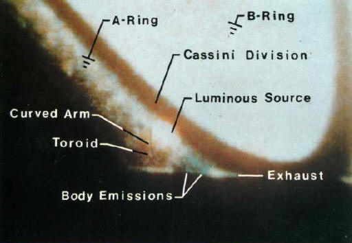
A luminous source appears in the A-ring of Saturn.
A number of luminous sources appear in Voyager imagery. One of these sources, located in the A ring, is documented in the photograph of Plate 3.
A pointer locates this source which appears as a small reddish-orange spot. In the picture, the A and B rings readily can be identified; and even some of the faint C ring can be distinguished. The Cassini division, pointed to in the upper left corner of the picture, clearly is formed by a separation between the A and B rings.
Diagonally in the opposite corner below the luminous source, a comparably formed Cassini division is absent. The B-ring outer edge is complete.
However, between points (1) and (2), the A ring is nowhere to be seen. A segment of the A ring appears strangely terminated across a chord of the entire ring system. Absence of this ring segment is addressed subsequently.
Conceptualization of the incomplete A-ring in a polar view of Saturn's northern hemisphere,
using Earth as a comparable
reference measure.
Earth profiles are introduced to provide a familiar reference measure. Line-of-sight is perpendicular to the ring plane so that all rings appear in true relative proportion. The length of the ring-segment chord is greater than Saturn's diameter.
This fact is illustrated by projection of parallel dotted lines from Saturn to the chord. These dotted lines intersect the ring chord within the cut-off segment of the A ring. The Enke division, placed at 2/5 the A-ring width from the outer edge, can be seen to intersect the chord at nearly the same points as the projected dotted lines. The distance subtended by the entire chord is equivalent to slightly over 10 earth diameters.
Only about 6 earth diameters comprise the radial distance from Saturn's surface to the A-ring outer edge.
Other distances also can be compared. For example, the radial span from the inner edge of the A ring to the outer edge of the Enke division is about one earth diameter. Span of the Enke division is expressed by a mere line width inasmuch as this gap is only about 200 km (125 mi) across. Radial span of the Cassini division is about 0.3 earth diameter. As before, Saturn's diameter is 120,660 km (74,980 mi). Circled numerals cross-reference the corresponding numerals shown in Plate 3.
Efflux from along the length of a slender body,
exhausting
at both ends, generates the A-ring. The luminous source seen near numeral (2) in Plate 3 appears at the left edge. Inspection of Plate 5 indicates that a slender body is orbiting clockwise and, in doing so, deposits a wide trail.
This trail, which can be recognized as the A ring without the Enke division, is generated by efflux emanating from nearly the entire length of the body.
While most of the efflux is generated along the top, some also appears to begin underneath and along the body sides in the form of streamers. These streamers pass over the side toward the right, proceed above the body and contribute to the A-ring trail. Presence of exhaust flames from each end of the body and the bulgy appearance of the streamers as they pass over the body suggest a circular cross-section for the body.
A light source, somewhat greater in diameter than the body, is positioned below the right end. This source is attached to the body with inter-connecting emissions turning to an orange-red arc along the top edge.
This physically inherent mobile capability is justification for calling the body a vehicle. *
* See Appendix.
The ratio of apparent body length to thickness, called apparent fineness ratio, is about 13 to 1. Absolute dimensions corresponding to fineness ratio 13 can be estimated.
Consider that the vehicle lies along the chord identified by numeral (1) in Plate 4, and that the vehicle extends from the A-ring inner edge to the Enke-division inner edge. By scaling the illustration in Plate 4, the body length is found to be about 0.3 Saturn diameter, or about 36,200 km (22,500 mi). This length corresponds to about 3 earth diameters.
Based on a 13 to 1 fineness ratio, the body diameter can be deduced to be 2785 km (1730 mi). This distance is about the same as the airline distance from San Francisco, California to St. Louis, Missouri on the Mississippi River. Such an immense propulsive body implies a space engine possessing unheard-of capacity and capability.
This source is the same one identified in Plates 3 and 5. Breadth of the source is estimated to be about half the distance between the A-ring inner edge and the Enke-division inner edge.
This sizing places the breadth of the luminous source at about 5600 km (3480 mi). This distance is slightly over 1 1/2 times the diameter of earth's moon and about the same as the airline distance between New York and London. The large magnitude attests to the vast energy powering the engine of the slender space vehicle.
A slender vehicle forms
an A-ring trail which includes a
luminous source.
This bulge appears to be a doughnut-shaped formation, or toroid through which the arm passes. Presence of a toroid indicates that the arm is acting as a conductor carrying electricity. Such an indication is given because physically a circular conductor of electricity has, in cross section, magnetic-field lines consisting of concentric circles (i.e., circles with a common center).
Magnetizable matter caught in such a field will align itself concentrically with the conductor and collectively assume a toroidal shape. Diameter of the conductor is in the neighborhood of 350 km (220 mi).
Length is of the order of 4000 km (2500 mi). Without this arm, maintenance of the luminous source probably would be impossible.
Preference is for the latter. Excluding bulb luminous sources, Plates 5 and 6 tend to show that vehicle diameter is an approximate measure of thickness of the A ring at inception. For the time frame shown then, maximum ring thickness inferentially would be of the order of 2785 km (1730 mi).
Obviously, at large distances from the vehicle, at the ring edges and for old trails, the ring would be expected to be much thinner and more diffuse.
Knight and Ainslie reported a luminous source as bright as a star. Both descriptions fit acceptably well that which is discerned from the three plates.
An additional commonality exists between the Knight-Ainslie event and the two vehicles in Plates 5 and 6. Specifically, the chordal path of the Knight-Ainslie moving source is the same chordal element defined by the location and orientation of the two vehicles. Whether these chords are in the same approximate position around the ring is beyond the scope of this inquiry.
Also, the extent of flux emission along the length of a vehicle can influence the width of the Cassini division.
These possibilities for differences explain the variability in measurements by different observers over the years. Fairly narrow tolerances, astronomically speaking, on the radius of the B-ring outer edge and the A-ring inner edge have led observers to conclude that the Cassini division is a true gap. That the Enke division is a true gap has been doubted because of its apparent absence from time to time.
Actually, the Enke division is formed in the same manner as the Cassini division and in this sense, the Enke gap is just as true a one as the Cassini gap.
Efflux emanating primarily from the radially outboard 2/3 of body length is responsible. Clearly, were the vehicle located at a slightly shorter radius, the gap would be lessened. Widths reported for the Enke division range from approximately 200 to 320 km (125 to 200 mi). Nominally, this gap width is equivalent to a variation in orbital radius of only about 1/4 of one percent.
The implication is that orbital radius
of vehicle position is set very precisely in order to have a gap
produced. Inspection of the vehicle reveals numerous jets issuing
from many different positions around and along the body.
Formation of the Enke division.
Each jet appears to consist of a series of bulbous swellings. Such swellings are indicative of the form of electricially charged flows known as pinched plasmas. Length of the vehicle appears to be about 10 times its diameter.
A dark jet crossing the body near the left end makes the vehicle appear as though there are two sections aligned longitudinally. In reality, the vehicle is integrally one. An attempt at sizing yields an apparent length of about 4700 km (2900 mi) and a diameter of 470 km (290 mi). Diameters of issuing jets are of the order of 0.1 to 0.2 body diameter, or about 47 to 94 km (29 to 58 mi).
The search produced another vehicle at the outer edge of the Enke gap. This second vehicle, shown in Plate 8, substantiates the process by which the outer A ring and the Enke division are formed.
In the plate, the Cassini division, the entire breadth of the A ring and the Enke division can be discerned. The outer annulus of the A ring, defined by the Enke division and the A-ring outer edge, again is found to consist of a trail deposited by a slender vehicle.
As before, efflux emitted from
around and along the body is the source of the trail. Were the same
profuse efflux to occur completely along the vehicle length, little
separation would prevail between the new trail and the older, inner
A-ring deposits.
A second vehicle substantiates the process
by which the
outer A-ring and the Enke division are formed.
Apparent fineness ratio of the vehicle is 13 to 1 as compared with 10 to 1 for the vehicle of Plate 7.
Sizing yields a length of about 5200 km (3200 mi) and a diameter of 400 km (250 mi). While the two vehicles roughly are comparable in magnitude and quite similar in certain respects, they also have differences. A notable difference is that the instant vehicle seems to have a longitudinal exhaust whereas the previous one very definitely does not.
Differences in length and longitudinal body-flux distribution lead to a difference in width of the Enke division.
For the shorter vehicle, Enke-division width is about one percent of the distance between the A-ring inner and outer edges. For the longer vehicle, the Enke gap width is about 6 percent of A-ring width.
Nominal values reported are in the range of 1 1/2 to 2 percent. A conclusion is reached that the A-ring outer annulus can be constructed with vehicles having different lengths and emission patterns. Therefore, the Enke gap can be located almost anywhere, or not at all, within the A ring depending upon length and positioning of the vehicles forming the inner and outer annuli.
In view of this possibility, the difficulty of early observers in pin-pointing a single radial location for the Enke division is now readily understandable. Inability to obtain unanimous opinion for ring thickness is also explained.
An apparent included angle of about 30
degrees is formed by two imaginary lines having a point of
intersection on the ring's outer edge.
Plate 9 Partially developed ring system
exhibiting a transversely
positioned cylindrical vehicle in the B-ring.
Body angularity less than 90 degrees with respect to the radial direction indicates that the vehicle occupies a slewed position within the ring. A slewed position is consistent with that observed for vehicles located in the inner and outer A-ring annuli.
At the left end, a short length of axial exhaust is detectable. An implication is that condensed and solidified exhaust products are the primary constituents of the C ring. At the right end, the axial exhaust stream can be identified passing through the A ring. Penetration of the stream through the A ring vaporizes in-path material and renders the ring discontinuous.
Also at the left end, three bulbous jets of matter are ejected. Towards the right end, three more bulbous jets emerge from a small common area. Quite likely all the bulbous jets are pinched plasma formations inasmuch as the presence of substantial heat in exhaust products is indicated. Emissions at other body locations are identified in the plate.
All the ejected matter, except for the right-end bulbous jets, provides intimate substance and texture to the B ring. The right-end jets rise above the vehicle, form an arch and connect with the A ring. Apparent fineness ratio of the body is in the neighborhood of 13 to 1.
Rough sizing places vehicle length at about 29,500 km (18,300 mi) and the diameter at 2250 km (1400 mi).
Plate 10 Emitting vehicle stationed outside the A-ring encompasses the F-ring location.
Shown in the plate outside the A ring is an emitting slender body positioned near the F-ring location.
Axial exhaust appears to emanate from the body ends, locations of which are identified. Issuing from topside at the right end of the vehicle is a long streamer which extends leftward toward the A ring.
This long streamer and the axial emissions are primary contributors to a massive cloud which forms in the vicinity of the vehicle. Secondary contributors are jets discharging laterally (not labeled). Highest cloud density occurs below the A ring near the right edge of the photograph.
This occurrence suggests a long axial exhaust emission which, owing to very elevated temperature, requires a considerable distance before the constituents reach the cloud-forming condensation point.
Lowest cloud density occurs below the body, attesting to the comparative minor nature of lateral and downward emissions. Intermediate cloud density is displayed between the trailing streamer and the A ring.
In the vacuum of space where the environmental pressure is practically zero, a cross-flow can occur only because of an electrical pressure difference between two points. An electrical pressure differential causes electricity or electrons to flow from the higher pressure to the lower one. These flowing electrons necessarily must come from a highly ionized volume of matter, an obvious source of which is the vehicle.
This situation again points to the reasonable presence of pinched plasma formations. Overall cloud breadth is estimated to be of the order of 3 earth diameters. Apparent fineness ratio of the vehicle is about 12 to 1.
The Cassini division and the Enke gap within the A ring are created simply by definite radial spacing of the respective formative bodies. The C-ring and the F-ring formations apparently depend upon the presence of a nearby vehicle. At birth, the A and B rings appear to have electromagnetic properties.
In view of the generating mechanism, heretofore confusing variations in observational results now become explicable.
Further, presence of a vehicle is likely whenever rings appear. Such likelihood is in consonance with the explanation for the A and B rings. Specifically, a vehicle-ring coupling exists because exhaust products and body efflux supply ring constituent material.
This coupling characteristic renders the expansive E ring, positioned roughly between 3 and 8 Saturn radii, a highly suspect candidate for additional activity. Orbiting within this 5-radii wide annulus are Saturn moons, Mimas, Enceladus, Tethys and Dione.
Rhea orbits outside the E ring at 8.7 Saturn radii. Conceivably, any of these moons might be shadowed by one or more of the massive and powerful slender vehicles.
Named clockwise starting at the upper right, the moons are:
The luminous image lies between Dione and Rhea. Superficially, this image would appear to be a moon-like object comparable in size to its adjacent companions. Logically, a question arises as to the validity of this image.
Is the image an artifact of processing, or does it indeed represent the image of a real object?
Position identification of Titan, Mimas, Enceladus, Dione and Rhea is consistent with later known positions of these moons.
However, the position of the luminous image between Dione and Rhea does not coincide with the calculated location of Tethys, the only possible moon candidate. Were Tethys in fact within the camera field- of-view, this moon ought to be visible inasmuch as its size is comparable to Dione and Rhea.
Because Plate 11 is devoid
of visual
depth, graphic pictorialization is helpful to gain further
understanding of the luminous image.
Saturn, five Saturnian moons and an unexpected luminous image.
Results are presented in Plate 12. This plate pictorializes the luminous image in positional relationship to Saturn, the A, B and E rings, six near moons and their orbital paths. Boundaries of Plate 11 are shown by dashed lines.
Calculations place Tethys about 2/10 the straight-line distance between Dione and Rhea, and in an orbital path whose radius definitely is shorter than that for the image. Discrepancies in both radial and angular positions of Tethys with respect to the image would indicate that the image indeed is not Tethys.
Because Tethys and Dione are very nearly equal in diameter (1050 and 1120 km respectively), a reason should exist for obstruction of Tethys' appearance in Plate 11. Certainly, this obstruction can not be caused by Tethys' two small companions whose largest dimension is of the order of 35 km and which, moreover, follow the same orbital path.
Also, little likelihood exists of
mistaking the companions for the luminous image because of their
exceedingly small size.
Pictorialization of luminous image in positional relationship
to Saturn, the A, B and F rings, six near moons and
their orbital paths.
Note that the dotted-line enclosure excludes Dione and that it does include the calculated position for Tethys. Also observe that Rhea is included at the extreme left, just outside the E ring.
The other end lies obscured behind a luminous jet which projects laterally leftward from the body.
Emissions issue in knotted rolls both above and below the lateral jet. These rolls develop an expansive labyrinth giving the E ring a cloudy appearance. The labyrinth below the lateral jet serves as a connection to the image. A second connection is created by emissions from the body.
Specifically, below the forebody, this connection is established through two nearly concentric toroids interconnected radially with roll segments, like spokes of a wheel. One of these spokes connects with the upper edge of the luminous image. This spoke, the two toroids, and a central hub are identified in the plate.
Presence of toroidal formations is considered indicative that the emissions have electromagnetic properties.
The two different connections between the body and image become paths by which a potential difference, or voltage, can be delivered remotely to a point in space.
Enlargement of luminous image
revealing a nearby slender
vehicle within the E-ring.
The reason is that proliferous efflux from the vehicle blocks Tethys from view. However, whether the image in the plate is, or is not, Tethys really need not be resolved conclusively. The important emerging fact is that all moons in the E ring can, at some time, be within immediate range of a vehicle capable of large-scale electromagnetic influences.
Also, consistent with findings concerning formation of Saturn's other rings, the E ring is caused by a vehicle spewing matter.
This multi-layer ring concept of the outer atmosphere carries the idea that strata might be vehicle related. In this context, presence of slender vehicles in Saturn's atmosphere would be a reasonable expectation. Easy identification, however, is thwarted because clouds (emissions) tend to obscure the sources being sought.
This difficulty, though, can be circumvented.
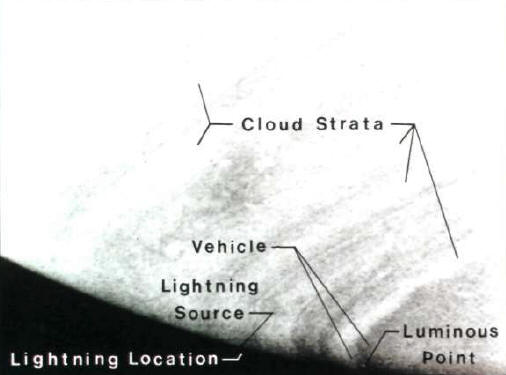
Plate 14 presents a sector of the southern hemisphere of Saturn showing cloud strata, a curious luminous point, location of a lightning source and a slender vehicle. In the plate, the luminous point occurs below a dark slender object, axially aligned with an overhead latitudinal cloud stratum.
This isolated body is labeled a vehicle because it has an apparent fineness ratio of about 13 to 1, and also because it evidences emissions. At the horizon left of the vehicle, a lightning source and a lightning location is indicated.
The source, a small "tick" protruding into space, can be
discerned upon close scrutiny.
Sector of southern hemisphere of Saturn showing cloud strata, a luminous point, location of a lightning source and a slender vehicle.
(Non-optimum exposure for overall picture favors
the dark region at planet horizon).
However, the intent at this juncture merely is to call attention to event locations. Imagery is clarified in the enlargements of Plates 15 and 16 used for subsequent discussions.
Luminous point of Plate 14 essentially is an arc light whose apparent power source is a remote vehicle
capable of
generating paths carrying electricity.
From the lower left end of the vehicle, a very long, slender element projects from each side. This element, labeled a bi-lateral projection, in turn issues other projections along itself. Several of these secondary projections lead to the luminous point. Connected to the point are a number of radial filaments which variously connect with the projections.
The result is that the luminous point becomes a center of mis-matched electrical potentials; and illumination is generated in much the same manner as for an arc light. Light diameter at the converging intersection of electrical paths is estimated to be in the neighborhood of 45 to 50 km (28 to 31 mi). Distance from the originating source of potential appears to be of the order of 500 km (310 mi). A characteristic of arc light is high thermal temperature.
Temperature of arc lights employing earth technology is limited chiefly by the melting temperature of the electrodes (analogous to filaments) which supply potential differential.
For carbon electrodes, this limit temperature is about 3700 degrees Celsius (6700 degrees Fahrenheit).
Even this modest temperature is adequate to melt most solids indigenous to earth. The luminous-point filament electrodes, in all probability, develop much higher temperatures. Because the isolated luminous point of light implies a current flow, which in turn implies a magnetic field, the conclusion is reached that the source vehicle and surroundings are electromagnetic in character.
To improve
visual orientation, the picture has been inverted so that dark space
occurs in the upper half of the frame and a small section of Saturn
in the lower half.
Two lightning bolts appear in and above Saturn's cloud tops.
Photograph is an enlargement of Plate 14 in the area labeled
"lightning location".
In the discussion of Plate 14, the terminology "tick" protuberance has been used in referring to the lightning source.
This plate reveals that adjoining points (1) and (2) really constitute the "tick" protuberance. The lightning location is clarified in that a lightning bolt emanates from point (1), and another is connected contiguously to point (2).
Length of the upper lightning bolt is estimated to be of the order of 400 km (250 mi).
Length of the lower bolt is of the order of 350 km (220 mi), for a total length of 750 km (470 mi). Bolt diameter is in the neighborhood of 10 to 12 km (6 to 7 mi).
Power to energize this impressively long path to luminous visibility can be traced to a cylindrical vehicle positioned directly below the lower lightning bolt. Helpful clues regarding vehicular presence are two "wishbone" shaped filaments, the spread ends of which straddle the cylindrical body.
Point (2) locates the tip of the larger wishbone filament and point (3), the smaller. Lateral spread in each of these filament pairs helps establish the body breadth and also the orientation of the longitudinal axis, shown added in the plate.
One end of the body appears to lie to the left of the lower lightning bolt about 3 bolt-widths away. Highlighting the left end is a luminous "exhaust stack" having a rounded leading-edge profile which presents an elliptical face. An elliptical end face is consistent with an angular view of the longitudinal axis for a body having a circular cross section.
The right end of the vehicle is considered to lie centrally beneath a U-shaped cloud bisected by a small roll cloud. Inferentially, the bottom tip of the lower lightning bolt would appear to originate from a port in the side of the vehicle.
Upon port exit, ejecta rise up across the body surface, then turn rightward to bridge points (3) and (2). Flow continues into pivotal point (1). At (1), the lightning-bolt direction changes abruptly to the left, traverses a sinuous path and then fades to completion at point (4). Point (4) lies at a distant secondary projection on the left arm of the bi-lateral projection.
A simple explanation for the progression and sustenance of the lightning bolt is that successively smaller electrical potentials prevail sequentially along the course.
Progressively reduced potentials would cause ejecta originating from the port to arc to points (3), (2), (1) and (4), respectively. These lightning bolts have some resemblance to terrestrial lightning, but they are far more immense in both length and breadth.
This immenseness implies an intense magnetic field having substantial far-reaching effect in terms of reacting with other existing fields. Many strange shapes might occur because of such interaction.
A propulsive body capable of creating such an environment, indeed, appropriately is called an electromagnetic vehicle.
The utter idea that the rings might be quite young is uncomfortable to primordial advocates because a key assumption is placed in jeopardy. Previous chapters have pictured several different electromagnetic vehicles actually depositing the A and B rings (Plates 5, 6 and 7).
These fortuitous pictures say not only that the ring material is quite new, but also that continuous regeneration can occur.
Conversely, ring extinction by vaporization is a realistic possibility. Vaporization could result consequentially from the immense, high-temperature luminous, mobile forms which can be generated. Exemplary forms are a fire ball larger than earth's moon (Plate 6) and a lightning stroke almost as long as the State of California (Plate 16). Yet still, these displays of power are fairly modest.
A colorful, large-scale narrow-band disruption
in Saturn's
rings extending across the entire ring system.
This dramatically colorful display, presented in Plate 17, gives the rings an appearance of being shifted rightward within a narrow band.
A discontinuity band, such as this, is rare in photographs of the A and B rings. Hence the phenomenon likely is aperiodic and of fairly brief duration - perhaps days, or even hours. In addition to the multicolored band, very narrow parallel markings can be seen extending chordwise across the rings in several locations. Further, two luminous sources appear in the right-hand sector of the rings.
One is positioned in the Cassini division above the discontinuity band, and the other is located just below the band in the A ring. Noteworthy, too, is the completely filled Cassini gap.
Usually, this gap appears mostly as empty space. An astounding 218,000 km (136,000 mi) is spanned by the colorful band, roughly the equivalent of 17 earth diameters. Band width is in the neighborhood of 3000 km (1850 mi), equivalent to about 3/4 the distance across the continental United States. Contained within the narrow rectangular area across the rings is an area of about 670 million square kilometers (approximately 260 million square miles).
Thus, the affected region exceeds the total surface of the earth, which is about 510 million square kilometers (197 million square miles).
Obviously, a disturbance of such great magnitude requires immensely enormous energy. Insight concerning the physical situation in and near the discontinuity band is provided by subsequent plates presenting enlargements embracing localities at points labeled 1, 2, 3, 4 and 5.
Another vehicle, labeled (2), pokes its nose slightly up out of the Cassini gap. Body ejecta and the luminous source hide all the body aft of the nose and also fill the Cassini gap. Each side of the vehicle (2) ejects a lateral emission, heretofore termed a bi-lateral projection in discussion of Plates 15 and 16.
This projection extends completely across the A and B rings, a distance of the order of 42,000 km (26,000 mi). Below the bi-lateral projection, a blue- colored niche exists on the inner edge of the B ring.
This angular niche is delineated by two skewed linear elements. One element is a vehicle, labeled (3), positioned at the upper left corner of the niche. The other element is a secondary projection, A-B, originating at a distant vehicle labeled (4). Vehicle (4). located in the A ring near the top edge of the picture, generates a leftward lateral projection from which the secondary emerges near B.
The vehicle and the terminal end of the projection colorfully interact to create the angular niche. The interaction creates the impression that the B-ring inner edge locally is shifted toward the right.
All these interconnected events are
occasioned by the presence of an electromagnetic vehicle.
Luminous sources provide clue to presence of electromagnetic vehicles
as a causative mechanism for a filled
Cassini gap and an apparent ring shift.
Vehicle and ejecta in the Cassini gap
in relation to an
A-ring discontinuity, apparent ring shift and a luminous source.
Within the spread of these pointers measured along the top element, about 2 body diameters of length appear in dark color. About another body diameter of length can be discerned covered with a mantle of cloudy efflux. Vehicular angular position is such that efflux from the top and bottom of the nose fills what normally would be the open Cassini division, or gap.
Axial exhaust, whose diameter measures about 1/2 that of the body, is projected into the A ring and creates a blue area there. A rope-like appendage, or tongue, is attached beneath the nose.
Above the nose, a stream of ejecta trails aftward and separates the A and B rings. This streamer consists of 5 interconnected nodules*, labeled (1) through (5). Each nodule grows a lateral trunk, the five Nodular streams are characteristic of pinched-plasm a flows and have electromagnetic Properties.
Trunk (a) is connected directly to the luminous source. Branches of trunks (c), (d) and (e) also are connected to the luminous source. Branch connections are made by an intermediate straight-line element labeled a transmission line. Between the end of the transmission line and trunk (a), a luminous arc is drawn. This arc, or luminous source, is about the size of earth's moon.
Structural manipulation of the A ring and development of such a large luminous source convey the sense of tremendous power inherent in the vehicle.
This view, introduced as Plate 20, shows the apparent ring shift and band discontinuities in relation to two electromagnetic vehicles in the Cassini gap. Picture orientation has been rotated clockwise 90 degrees to facilitate feature recognition. One vehicle is labeled (1), and the other (2). Each nose position is indicated by a pointer.
Both vehicles have substantial angle-of-attack with respect to the ring plane, perhaps as much as 30 degrees.
Consequently, the aft end of each is below the ring-plane surface and, therefore, not identifiable directly. Unique emissions, or ejecta, along the body length confirm vehicular presence in the Cassini division.
The two projections provide the horizontal and vertical boundaries of the niche which, impressionistically, appears as a local shift of the ring. Cassini-gap filler substances are produced for the most part by various emissions along top elements of the vehicle body. Nose ejecta also contribute. One of the sources of filler substances is a hemispherical unit, or "turret" located about 2 body diameters aft of the nose.
Other sources are nodular streamers which are discharged directly from the body surface. Two such streamers, a large and a small one, are identified in the plate. The base of the larger one is positioned about 4 body diameters aft of the nose. The smaller one starts slightly aft of the larger one.
Contributing nose ejecta take the form of a knotty curvilinear jet, or tongue, which protrudes from the bottom of the nose. A secondary projection is emitted vertically downward from this tongue and causes the right-hand discontinuity across the B ring.
Plate 20 Apparent ring shift and band discontinuity in relation to two electromagnetic vehicles in the Cassini gap.
Slightly outboard of the body, a downward secondary projection develops from the uni-lateral projection to which other body side-emissions contribute.
The two downward secondaries supply the discontinuity boundaries of the apparent band shift. Cross flow directly connects the secondaries above the uni-lateral projection. Below, the uni-lateral projection itself interacts with the two secondaries to create somewhat of a diagonal flow.
An additional element associated with vehicle (2) is a junction located at the B-ring inner edge, functioning as a terminator for the uni-lateral projection. Having planar sides, this junction is tremendously interesting. Planar shapes can be constructed with electro-potential fields, but only with appropriate field combinations.
Hence, such combinations are not likely to occur by chance. Inferentially, applied intelligence would seem to be required.
Plate 21 reveals braided strands, a braiding unit and cross flow between discontinuity-band boundaries.
Plate 21 Braided strands, a braiding unit and cross flow between discontinuity boundaries at the B-ring inner edge.
Creating these discontinuity boundaries is the familiar pair of secondary projections originating at an electromagnetic vehicle in the Cassini division (Plate 20). The projections, labeled (1) and (2), have about equal diameters and are spaced on centers about 6 diameters apart. Attached to the side projection of (1) is a pair of tightly braided strands (a) and (b).
These strands are not connected to the side of projection (2) in the same manner as for projection (1). Instead, a connection is made to a stubby protuberance thereon.
Distributed around the protuberance, or braiding unit, are individually attached strands comprising braided strands (a) and (b). While these separate strands appear quite narrow in the picture, actual width is about 90 km (56 mi). Considering that the originating source may be as much as 45,000 km (28,000 mi) distant, such flow is quite remarkable. Issuing from the end of projection (1) are two filaments (a) and (b).
One, (a), is positioned near the upper part of the terminal face; and the other, (b), is located centrally. End-flow filament (b) forms an arch between projections (1) and (2). Cross flow between the projections occurs because of a relative potential difference. Arching is due to the potential causing reorientation of the initial flow direction.
B-ring emissions become C-ring constituents.
Filament (a) can be seen for the first time to extend about midway across to the opposite B-ring edge. Near the mid point, M, the flow arches back to a point, P, at the B-ring inner edge, analogous to the return of filament (b) to projection (2). The re-entrant flow element from point M is labeled filament (c).
Emissions from filaments (a), (b), (c) , the bi-lateral projection and other points along the B-ring inner edge fill the entire central ring system. Lying adjacently within the B ring the emissions comprise the region commonly designated the C ring. However, no inner edge exists to delineate a boundary between the C and D rings. For this particular sighting, therefore, the D ring must be considered non-existent.
C and D rings have been observed in the past, and undoubtedly will continue to be observed in the future. this plate indicates that their occurrence is dependent upon electromagnetic vehicles in the ring system. Specifically, the rings are related to vehicle positioning and degree of emission activity.
Alignment and positioning of vehicles on the left side of the ring system is found to be distinctly different from that on the right side. Yet, the narrow discontinuity band across the entire ring system is aligned quite in a straight line. Restated, several independent events acting in concert are required to create the linear, uniform-width discontinuity band across the tremendous span of chordwise opposite rings.
Ordinarily, only a single causative agent is dominantly responsible for an event.
Here, however, at least 7 powerful agents of like kind are involved. In this situation, intelligent coordination would appear to be a more reasonable presumption than a chance occurrence of numerous simultaneous events. Even were the band caused by a single exceptionally large unit, the discontinuity band can be regarded as something of a big show.
After all, the band is not at all a prevalent feature of the Saturnian ring system. Indeed, attention paid here may be the first directed specifically to this phenomenon. Viewed then as a rare show of power, the uniquely colorful band probably holds the distinction of having been constructed deliberately. This likelihood is enhanced by the finding that the A and B rings, in fact, are constructed.
Formation of the cross-system band and generation of the A and B rings both imply that indigenous to electromagnetic vehicles is a portentous controlling power.
Specifically, the A-ring components are the inner and outer Enke rings and the separating Enke gap. Separating the F ring and the A-ring outer edge is a distance of about 3700 km (2300 mi), labeled (d). Distance (d) is nearly the same as the width, (w), of the outer-Enke A ring (3200 km or 2000 mi). In terms of earth traverses, (d) and (w) are roughly the same distance as an airline flight between Washington, D.C. and Los Angeles, California.
Breadth of the
F ring,
(e), is about 70 to 100 km (40 to 60 mi), or about 1/3 the Enke-gap
width. At the left, a shepherding satellite marks a segment, A, of
the F
(b) Region (2), plate 23 ring having pronounced luminosity.
Non-uniformly luminescent F-ring in positional relation
to
A-ring components and a shepherding satellite.
(b) Region (2), plate 23
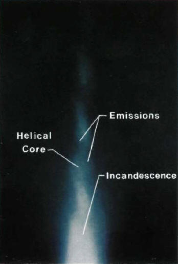
Segments of F-ring close-up showing that luminosity derives from emissively active core material.
Right of (1), a break in the ring occurs at B. Following this break, a pattern of variable luminosity continues along the ring to the right. Maximum brightness is achieved at the segment labeled C, even though a shepherding satellite is not present and the ring is discontinuous. Therefore, some sort of excitation mechanism exists, other than shepherding satellites, to produce variable luminosity along the F ring.
Part (a) presents a segment at region (1) and part (b) shows a segment at region (2). At region (1), the finite segment has a clumpy, but untwisted core. In contrast, the continuously tapered segment at region (2) has a helical core as though composed of two or more entwined strands. Both regions exhibit stubby, luminous emission jets. Some of the emissions act collectively to produce areas of intense brightness, or incandescence.
Plates 24(a) and (b) disclose that the F ring consists of a high-energy train of material, neither everywhere continuous nor everywhere of uniform cross section. This type of irregularly-shaped emissive material, for convenience, shall be referred to subsequently as luminoids.
Plate 25 presents the non-uniformly luminescent F ring of Plate 23 exposed to reveal interconnections between the F ring and the A-ring outer edge.
While numerous inter-ring connections are present, two of the more distinct ones are pointed out in a region along the A-ring outer edge where filaments cross. Edge filaments are a product of various electromagnetic vehicle outputs which, as already has been found, extend throughout the ring system.
Functional compatibility of the A and F rings leads to a realization that the F ring is not an isolated entity. Rather, the F ring is an integral formation in the overall ring system.
A photograph of this braided F ring, exposed to bring out latent
background information, is introduced in Plate 26.
Non-uniformly luminescent F-ring of Plate 23
exposed to
reveal inter-connections between the F-ring and A-ring outer edge.
That part of the object which lies within the picture extends completely across the frame, up to a height (x) from the bottom edge. A relatively light color, in contrast to the upper background, delineates the area just described. That the light area is in fact an object is assured by the presence of two concentric circles whose center, (o), lies on strand (l). These circles are indicative of a circulatory magnetic field around center (o).
Additionally, surface patterns and shading suggest that the top horizontal element lies farther away than the element along the bottom edge. Further, strand (2), is straighter above the surface-departure point, (a), than below it.
The greater curvature of strand (2) between the point of origin and departure point (b) suggests a rounded surface. If this rounded surface is taken to be a circular profile, its radius would be about equal to the distance labeled (x).
Half-diameter (x) is about seven times greater than the width, (w) of the F ring. When (w) is taken conservatively to be about 100 km (60 mi), diameter of the object would be 1400 km (870 mi), very nearly half the diameter estimated for the vehicle of Plate 5.
Photograph of braided F-ring exposed to reveal a large
coupled object.
Spatial separation of the strand departure points sets up the initial condition which leads to braiding. Once departed, the strands tend to entwine owing to the inherent magnetic fields attendant with constituent luminoidal emissions. At least for the one case of Plate 26, luminoid strands originate from a very large, quiescent object.
Knowledge of the specific luminoid source cannot be determined with a high degree of resolution because of paucity of data. There are, however, several highly suspect vehicle components quite capable of producing the F-ring trail of luminoids.
An obvious component is the nose section of a vehicle when protruding sufficiently beyond the A ring. While the nose section of a vehicle is somewhat more active compared with its rear section, activity near the nose could be quite sufficient to generate luminoids (Plates 7 and 8).
Luminoids also might be generated from vehicular axial exhaust products, separately or in conjunction with tip matter from trailing body streamers. Moreover, this latter mechanism is compatible with activity between the F ring and the A-ring outer edge (Plate 25).
Luminoids might be expected to be found elsewhere in the Saturnian satellite system, albeit not necessarily active or in ring form.
Presence of these units is made fortuitously clear in Plates 5 through 8. Ordinarily, emissions are so profuse and chameleonic in character that recognition is rendered quite difficult. Recognition also is hindered by different modes of vehicle operation which produce strangely diverse appearances. In absolute size, these mobile bodies are unearthly large.
However, in terms of typical Voyager photographic fields of view, frontal body images are close to being imperceptibly small.
Feature recognition, therefore, is in part a developed skill of geometric perception in relation to surroundings. Cognitive skill is deterred when one has never performed the exercise of examining and correlating numerous photographs.
Lest this deterrent have caused difficulty in relating to reality of size, this chapter shall approach earlier subject matter from a different viewpoint. Then, consideration will be given to two close-ups of Saturn which will provide information transitional to subsequent chapters.
Ratio of length to diameter for all is in the neighborhood of 13 to 1. Given the premise that the small and intermediate units together generate the A ring, a fair inference is that a single larger vehicle similarly might generate the B and C rings.
A single vehicle is inferred because no gap exists between the B and C rings. If these observations really are true, then it follows that ring size must be a fairly good measure of vehicle size.
These sizes closely satisfy the Planar dimensional requirements for
forming the A, B and C rings.
Three fineness-ratio 13 vehicles having multiple unit sizes of 1, 2 and 4 closely satisfy tin- planar dimensional requirements for forming the A, B, C and D Saturnian rings. View is perpendicular to the ring plane.
In the polar view shown in the figure, the bottom element of each vehicle is a line, which, when extended, perpendicularly intersects an extended Saturnian equatorial diameter.
Intersections of these line pairs mark points of tangency of the vehicle body-element lines (extended) with respect to ring-gap boundaries. For example, the tangent point for Vehicle I is at the Enke gap; for Vehicle II, it is at the Cassini gap; and for Vehicle III, it is at the surface of Saturn.
When 12,669 km (7874 mi) is taken as the unit length, Vehicle II is twice the size of I; and Vehicle III is twice the size of II. Vehicle lengths in terms of Earth's equatorial diameter are 0.99, 1.99 and 3.97, respectively.
Even Vehicle I, the smallest, is large in that its length is almost the same as Earth's diameter. Vehicle III is much more immense. A circular disc having the same cross-sectional area as Vehicle III would cover the United States coast-to-coast, and extend from the south-western shore of Hudson Bay, Canada to Matzalan, Mexico.
Intermediate-size Vehicle II (1949 km diameter) has a frontal area which compares favorably with the size of Saturnian satellite Iapetus(1460 km).
These two positions are labeled (1) and (2).
The skew angle is formed by two lines which pass through the vertex: one line is the bottom element whose extension is tangent to the inner adjacent ring and also perpendicular to a Saturn radius extended to the point of tangency (dashed lines); the other line is tangent at the vertex to the inner ring being formed as well as perpendicular to a Saturn radius drawn to the vertex (solid lines).
In effect, the initial angle at which a leading-edge nose streamer trails back over the body of the orbiting vehicle is equal to the skew angle. To maintain constant width of the inner-Enke A ring, then, a vehicle must continue in orbit holding a constant 15-degree skew angle.
A larger skew angle implies a wider ring. Thus, differing measurements by various observers for inner- and outer-Enke A ring widths can be accounted for by variation in skew angle by these ring-forming vehicles.
A simplified electromagnetic vehicle in different attitude angles
for two orbital positions during formation of the inner-Enke
A-ring.
To attain this condition, the vehicle first must be rolled clockwise 90 degrees. In this position, the streamers shoot up and out of the ring plane. To get them back in, the tail end must be lowered so that the body is inclined 15 degrees to the ring plane.
When this is done, streamers are made to flow into the ring plane.
Thereby, identity readily is established. For either of these two situations, Plate 28 illustrates that an equatorial view alone will provide little cognitive assistance. In flight attitude (2), vehicle presence is fairly easy to establish.
The reason is that the nose protrudes slightly beyond the location of the furthest-forward trailing streamer. Though little of the body can be seen in a top view, a partial revelation does not mean that the rest is not there. In the equatorial view of Plate 28, a vehicle exhibits a large profile when in the attitude of position (2).
Therefore, one could think that detection might be easy. Unfortunately, cloudiness from lateral body emissions tends to hide everything. Nonetheless, mere identity of a single recurring feature, such as the nose, may lead to observation of other new features and modes of operation.
Atop the object, stubby emissions point outward at angles slightly different from one another. These different pointing angles impute an underlying curved surface.
Surface curvature
further is confirmed by a circular orifice which appears elliptical
because of being viewed sideways as well as frontally.
A dark blue latitudinal stripe in Saturn's atmosphere
emanates from an object identifiable as a probable electromagnetic
vehicle component.
A small toroid located at the base of the exhaust orifice attests to the electromagnetic character of the immediate locality. Below the toroid and orifice, a hose-like appendage or tongue projects longitudinally. Adjacent to the toroid, two arched azure-blue plumes are emitted from the tongue surface. These plumes contribute to the regional glow.
Further down, plume generation becomes quite profuse and enlarges the glow. At the edge of the azure- blue region, plumes can be seen to braid and knit themselves into a tight mass. This mass, which forms a long continuum of the tongue, appears as a stripe in Saturn's outer atmosphere.
The stripe is placed longitudinally whereas the body's longitudinal axis is displaced considerably from the latitudinal. Attitude adjustment to accommodate placement of exiting matter is typical for electromagnetic vehicles (Plates 18 and 28). Indications are that the object pictured probably is the exposed nose of an electromagnetic vehicle.
A component, (1), is identifiable readily as the nose orifice. Extending from below the orifice is a long, tightly twisted tongue, (2) The top longitudinal-profile body element, (3), is perceptible for a short distance aft of the nose.
Location of the bottom
longitudinal-profile body element is obscured inasmuch as a solid
band of under-body emissions, (4), exhausts where this element
otherwise would appear. The distance between these two locations
establishes an approximate body diameter, (5), and permits
estimation of trailing-end location.
Plate 30
Salient features of an operational electromagnetic
vehicle.
Back at the nose a bi-lateral projection, (8), can be identified extending on each side. Branch streamers, (9), rise from this projection and flow centrally to form a large overhead annulus, (10). Secondary streamers.
This roll, in turn, emits filaments which contribute to the luminous sources.
Filaments exiting from the sources complete an electrical path upon termination at outer-boundary trailing streamers, (14). The electromagnetic character of these phenomena is affirmed by presence of nodules, (15), on streamers just aft of the annulus. These nodules, being visual properties of pinched plasmas, are indicative of electromagnetic interactions.
Length of body lateral projections appear to reach at least a body length, if not farther.
The projections in the picture extend outboard such that their terminal emissions, (16), form a well-defined latitude boundary on Saturn. Between the body and terminal emissions, body projections leave wakes of matter, (17), along their entire lengths. Literally, rivers of electrically charged matter flow from the entire body and affect vast areas. By any worldly standard, this display of organized power is profoundly awesome.
In the order discussed, the following are labeled for ready identification:
A cylindrical body, (1), emits a faint axial exhaust flame, (2), of probable extremely high temperature. Diameter of the exhaust orifice is about 1/2 body diameter.
Aft of the nose about a body-diameter
distant is located a bi-lateral projection, (3).
Plate 31
Front-end appearance of an electromagnetic vehicle as
rendered from Plate 30.
Below the projection is positioned a lengthy bank of under-body emissions or flame jets, (4). In frontal view, these jets would extend radially outward from beneath the body at a probable angle of about 45 degrees. Immersed in, but extending out of, the flame bank is a tightly entwined tongue, (5).
The length of the tongue is at least 2 body diameters and has capability within itself to project emissions or plumes. Atop the body nose just aft of the axial exhaust flame, a bulbar pinched streamer, (6), flows upward and aft.
This phenomenon illustrates the presence of different electrical potential (voltage) levels and demonstrates the mechanism that governs flow paths. Also in this same vicinity, numerous small radial emissions occur around the exhaust cowl. The hub labeled (10) acts as a collector to coalesce beginning streamers.
Coalescence forms an embryonic streamer which ultimately bursts forth.
Because of the natural propensity for emissions to seek the least path of resistance to attain a lower potential, all objects having a lower relative potential are subject to electromagnetic inter-action in some degree. How influential it is, of course, depends upon the distance between the electromagnetic components and the object.
Clearly, hot parts of a vehicle could leave imprints on large solid objects, as though branded. Saturn's rings exhibit some of the many residual forms which ejected matter can take.
Because of their mobility, vehicles can be expected to appear almost anywhere. A signature of former presence would be unique, solidified objects of appreciable size and differing shapes. Ejecta of different colors equate to different substances, or compounds. Interestingly, water in vapor, liquid or solid state most likely is a major and prolific exhaust product.
This assertion is based upon indications that Saturn's great rings are composed of water ice.
Vastness of range in vehicular capability further is indicated by large-scale formation and huge, sustentative luminous sources.
|