|
CHAPTER – 20
KRITAKA VIMANAS
Four Types of Vimanas:
The last few sections of the work
Vymanika Shastra deal with four
types of kritaka vimanas, Shakuna vimana in the lead.
Twenty-five vimanas of this category of the current Yuga are stated
as follows:
-
Shakuna
-
Sundara
-
Rukma
-
Mandala
-
Vakratunda
-
Bhadraka
-
Ruchaka
-
Virajaka
-
Bhaskara
-
ajaavarta
-
powshkala
-
Viranchika
-
Nandaka
-
Kumada
-
Mandara
-
Hamsa
-
Shukaasya
-
Sowmyaka
-
Krownchaka
-
Padmaka
-
Symhika
-
Panchabana
-
Owryaayana
-
Pushkara
-
Kodanda
The text Manibhadrakarika, quoting sage
Gowtama as also Shounaka
sootra indicates the same number of vimanas in the same order.
This
perhaps reflects that both the sages had the same origin of study.
Prescribing specific alloys for the structure of Kritaka variety,
the text Kriyasara dictates use of Raja-loha. This prescription is
echoed by Vishwambhara also. The process of manufacture of Raja-loha
is discussed in brief.
Here all the three Ooshmaapa core-metals
figure.
Soma, Soundala and
Mourthweeka in proportion of 3:8:2 mixed
with borax and melted 272 ° and churned form this alloy.
Observations:
-
While Shakuna,
Sundara and Rukma appear in the list, Tripura
vimana discussed in the work is conspicuously missing. In fact,
Tripura does not feature among vimanas of Tretha and Dwapara
categories as well.
-
The core metals of heat resistant variety discussed under the
Lohadhikaranam form the alloying components of Raja-loha. This
indicates continuity from the said chapter and the current one.
-
Lohadhikaranam dealt with core metals of specific thermal
resistant variety. Raja-loha among them is an exclusive alloy
developed for very specific properties.
Shakuna Vimana:

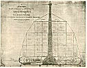

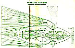
This vimana contains twenty-eight parts. They are Peetha or
Floorboard; hollow mast; three wheeled keelakaas; four heaters; air
suction-pipe; water jacket; oil tank; air heater; heater; steam
boiler; viduyut yantra or electric generator; air propelling yantra;
vaatapa yantra or air suction pipe; dikpradarshana dwaja; shakuna
yantra; two-wings; tail portion; owshnyaka yantra or engine;
kiranaakarshana mani.
Constructional aspects of the vimana are given too briefly and also
without clarity. However, from the English translation (literal and
frequently sprinkled with modern terminology) we have made an effort
to analyze. Floorboard is a sheet-metal structure made of Raja-loha
options have been offered to make the shape circular, rectangular or
cradle shaped. Weight of the Peeta or Base is one hundredth of the
total weight of the plane. Width of the peeta is half the height of
the mast. Hollow mast is to be erected by suitable joinery at the
center of the peeta.
Lallacharya quoting yantra-kalpataru prescribing only Haatakasya
metal for the mast or stambha specially describes hollow mast. In
this particular case a quadrangular base with two ends converging
into triangular form has been opted. Hollow mast or Naala stambha is
a three tiered-construction inside and outside diameter reducing
with each tier upwards. Wheels provided on the length of the
Hollowmast are not meant for movement of the vimana. From the
description available two outer fixed wheels and the central
rotating wheels, some kind of a compressor / turbine arrangement
seems to be under discussion to obtain higher pressure and velocity.
Window-Dome provided at the top of the vimana accommodates the sun
crystals crowning the dome. Sun crystal is big in size. In the three
vertical tiers of vimana, the first tier rests on the peetha. They
are separated by thick floorboard. First floor houses four heat
engines at the corners. Supporting pillars in the ground floor
accommodates passenger cabin. Second floor or tier accommodates
angayantras.
Below the ground floor a cellar houses some yantras, four air
compressors are provided and around the bottom of Hollow-mast. Air
compressors are supposed to be driven by steam power.
The arrangement described for the wing is interesting. The wings are
made of a number of feather-like structure stacked one over the
other and move around a common pivot. They can open out or close as
seen in a feeler-gauge. The wing will also flap along hinged joints
to generate lift.
A separate tail plane to facilitate elevation or take-off is
provided. As per the description the heat engine drives the
propeller to produce usual aircrew action. Controlling of wing
feathers and tail units is through control cables originating from
the cockpit.
Ignition of the oil (fuel) seems to be by electrical means. For
storing compressed air leather bellows have been suggested.
Observations:
-
Preparation of
Hatakasya alloy has been covered earlier in this
report.
-
Construction of the structure and a hollow mast hints at attempts
to achieve streamlining.
-
Units of measurement like Vitista needs to be verified and
established conclusively.
-
Three sets of wheels along the length of the hallow mast, hint at
their being power developing source. Wheels for the movement of the
vimana on ground are separate.
-
Use of sun crystal is obviously for solar energy extraction.
-
Use of steam power to drive air compressor seems to be strange
since steam generation during flying is itself strange.
-
Possibly Shakuna is one of the
early variants of Kritaka type,
deriving its name from the basic definition of bird. Hence the
arrangement of flapping and spreading wing and tail construction
feature.
-
In essence Shakuna is a rudimentary type with aircrew arrangement.
Sundara vimana:


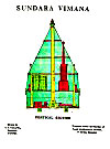
Eight constituent parts are:
-
Peetha or ground plate Smoke chimney
-
Five gas engine Bhujya metal pipe
-
Wind blower Electricity generator
-
Four phased heater Outer cover
Peetha or ground plate of Raja-loha with options to have square or
round shape. In the centre of the peetha Dhoomaprasaran Naala or
pipe is provided. Hollow mast is a tall cylindrical member with
provision to store gas energy at the bottom portion. Water vessels,
oil tanks are housed at the centre. At its foot electricity is
stored in a container.
Oil container will have three oils: Dhoomanjana oil, Shukatundalika
oil (eggplant oil) and Kulaki or Red arsenic oil in the ratio of
12:20:19. Ignition of the oil mixture is by electrical means.
Distribution of gaseous products seems to be through a special
arrangement ensuring even spread of gases. Dhoomodgama yantra is
meant to eject gaseous mass with speed. In constructing this only
Dhooma garbha loha with composition of Himasamvardhaka, Soma and
Soundala metals have been specified. Control of high-energy gaseous
products is through revolving wheels (possibly to operate valves).
Description indicates a hydraulic accumulator type of arrangement
for storing gaseous product. Ignition of oil is achieved by combined
process of electrical energy and friction.
Actual thrust is obtained by passing the high-energy product through
a number of Sundalas or Jet nozzles. This obviously seems to be
based on reaction principle. Manufacturing process of Sundala (made
out of special metal-impregnated fabric, flexible, heat-resistant)
as given by Lallacharya is explained in brief. These sundalas or
naalas are kept rolled-up over revolving drum while not in use. They
are unrolled and kept taut while in use. The gaseous products get
discharged through a number of them in jets producing thrust.
Generation of electric power has also been briefly covered. The text
talks of 32 types of machines to produce electrical power. Different
methods broadly stated are friction, by thermal process, by
waterfall, by combination of all these and also by solar rays. This
technology is ascribed to sage Agastya in his work Shaktitantra.
Electrical power production is described using four vessels located
in four directions and a central vessel. Several types of acids,
dravas are used in each vessel. Crystals or Manis such as Vidyutgama,
Jyotirmukha play a key role.
Extensively treated lion’s skin and deer’s skin (possibly for their
high insulation properties) figure in the process. Central vessel
forms the accumulator of electricity generated. Anshupa Mani or
Solar rays absorbing crystals is the main medium that absorbs heat
that gets converted to electricity through a process not clearly
described. The process of storing electricity by use of mercury has
also been brought in. Stored electricity is conducted to all parts
of the vimana through insulated cables for operating various
services.
Vataprasaran yantra is described as one to generate the main Udgama
Shakti or lifting force. This yantra comprises of twelve parts,
including Naala-Stambha, valves regulating inlet / outlet for fresh,
compressed air, exhaust, air guides, vanes. The system includes an
air compressor. The description hints at using compressed air jet to
obtain thrust. Further description mentions that compressed air
conducted through Naala sthambha and energy product by Dhoomodgama
yantra through the inside of the main mast or Bruhad sthambha. They
confluence at the end and go out through sundalas with high
velocity, effecting jet propulsion.
As stated for Shakuna vimana,
Raja-loha is used for structure and
covering of this vimana also. Chaturmukha or Oushnya yantra is the
main heat engine. Comprising of 18 parts this includes, Peetha,
Smoke accumulator, Oven, Water container, Valve controls, smoke
opening, Regulatory valve, heat indicator (temperature), Time clock,
Speedometer, Sound-transmitting instrument, Anthardhanda Ghata, air
bellows, Long sundala pipes, Copper pipes etc. Sundala used as jet
nozzles to obtain thrust are also used for vertical and aft
movements and directional control of the craft. Computation of speed
claimed to be achieved needs a re-look. The thrust from each
contributing source seems to have been added up. Retranslation of
many verses in this chapter may help in better understanding.
Observations:
-
Use of specific types of oils suggests that high-energy potent
fuel be under discussion.
-
Some error is noticed in the direction of movement of the craft
vis-à-vis jet stream from sundala nozzles. Applying the principle of
reaction the movement of the craft should be in the direction
opposite to the thrust line. Possibly this aspect is dealt by Swami Dayananda Saraswati in his
Rigbhashya Bhoomika. Incidentally this is
quoted in the report of I.I.Sc Bangalore also.
-
Very importantly solar energy employment for producing electricity
is a unique feature. Probably this technique was not heard of even
by the middle of 20th century.
-
Use of sundalas, as jet nozzles are again interesting. Operating
each sundala independently and varying mass-flow and velocity of jet
separately, multiple degree of craft control should be available.
Rukma vimana:
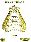


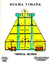
The description of this
vimana is too brief to comprehend the
principles of working. Rukma meaning gold, the vimana has been so
named because of its appearance of golden colour. Impregnating gold
colour on Raja-loha precedes fabrication of structural part of
vimana. Yantra-Bindu and Varna Sarvaswa explain the colouring
process. From the manner described it is not a plating process.
Peetha is stated to be tortoise shaped of length 1000 ft. This
however is too long and needs translational, interpretational
verification as well as equating units of measurements of length.
The other parts are Ayaschakra pinda and Batimikaa sthambha.
Description of flying lacks clarity. However, utilization of
electrical energy to operate Electro-Mechanical arrangement to
enable vimana to lift off and accelerate is hinted. A speed of 105
kroshas or 250 Mph. per ghatika is stated. Directional control as
suggested by Lallacharya is through conventional rudder system
provided at the base and articulated through crescent shaped plate
by means of push pull rods.
Observations:
-
Pushpaka vimana of epic
Ramayana is also described to be golden colour and delightful looking. Aesthetic sense of the scientists to
cater for the needs of the Royale manifest here. Gold colour
imparted to Raja-loha is before the alloy is used in structural
part. In fact it is built in the alloying process itself to make it
an integral part of the metal.
-
We note that the earlier two vimanas discussed did not mention of
gold colouring.
-
Rukma is stated to reach speed up to 250 miles in 24 minutes, a
speed of 725 miles per hour.
Tripura vimana:
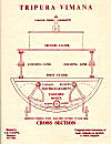


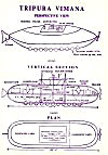
Tripura is the last of the representative vimanas discussed in the
text. It has two unique features. It is a three-in-one craft and
also a solar powered vehicle. Tripura means three storey or tiers.
This concept is brought in the form of a three-tier construction.
The first tier is for operation on land, the second one for
operation on water and inside water and the third for flying in air.
As an integral unit of three tiers the craft is stated to be a
flying machine. Differential use of first and second tiers
independently for movement on land and water is stated to be
possible.
In contrast with the other three vimanas this is to be
made of mica
(first floor) and Thrinetra loha (second and third floor). The
arrangement talks of wheels provided underneath peetha for
locomotion on land through electric motor. The wheels are retracted
from the ground before vehicle moves into water in amphibian mode.
During movement on water boats provided on the deck possibly to act
as buoys.
Detailed manufacturing process of obtaining particular type of
mica
has been dealt at length. Layout details of the first floor include
provisions for aisle, cabins for crew and passengers and storage
enclosure. Covering of the first floor is by water / air proof
fabric, easy to install and dismantle.
Second floor is proportionately smaller than the first. Electric
power is provided to second floor as well. When the second floor
gets into water the open hatches of the wheel will be covered by
special milk-cloth having full water proof property. Supply of air
to the second floor is ensured through ducts made of milk cloth.
This air under pressure is meant for comfort of personnel in first
and second floors.
For protection, safety and comfort of crew and passengers
three
separate yantras are provided viz., one to protect against stormy
winds, the second against solar-blaze and the third against
rainstorm. Construction of the third floor is similar except that it
is proportionately smaller. The special feature in the third floor
is that it houses electric generator. The cabin for this is to be
made of Somaka-loha.
The procedure for extracting electric power from solar rays has been
mentioned. Vessels and tubes made of Anshupa glass of a specified
variety and some electricity generating crystals participate in the
process. Anshupa and Sanjeeraka crystals play the primary function.
Purpose and function of Ganapa yantra discussed in the text needs
separate study with suitable interpretation.
Observations:
-
Three-in-one concept includes amphibian and under water modes of
the vehicle as well.
-
Use of solar energy for powering an aircraft is a unique
phenomenon, heard for the first time in the aviation technology.
-
To highlight the features of Thrinetra-loha, it is flame proof,
unbreakable, waterproof and above all, weightless. It has the Shane
of peacock feather.
General Remarks on Vimanas diagrams and drawings:
Inclusion of diagrams and drawings was an add on activity by
Sri. Shastriji from 1918 – 1923 AD.
This was done through a local
draughtsman under the pandit’s guidance. It is difficult to accept
that this process also was under the divine influence. It appears
that in projecting the contents of the work through pictures and
drawings their own interpretations seem to have influenced. Possibly
this has corrupted narration to some extent.
We are therefore not
inclined to accept the drawings till further study. It is learnt
that attempts are under way to build a prototype of one of these vimanas by a researcher in Hyderabad.
Go Back
|