|
Illustrations
from
TimeVehicle Website
-
Fig. A1. The Magnocraft.
-
Fig. A2. Various flying arrangements
and configurations formed by magnocraft.
-
Fig. A3. Scorch marks left on the
ground by landed UFOs.
-
Fig. A4. The eastern edge of the
Tapanui crater where UFO vehicles exploded in 1178 AD.
-
Fig. A5. Examples of underground
tunnels evaporated in rocks by UFOs.
-
Fig. B1. The 550 million year-old
imprint of human foot.
-
Fig. B2. An old church painting
portraying the Crucifixion of Jesus supervised by UFOs.
-
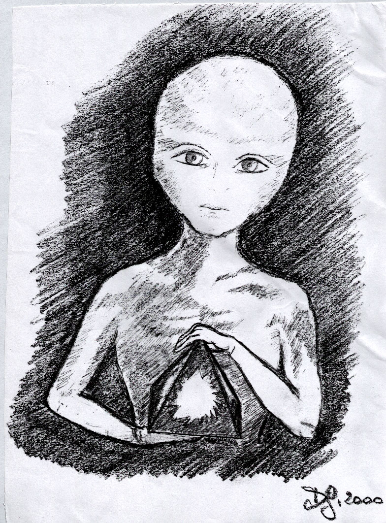
Fig. C1. The little white being with
blue eyes holding the pyramid.
-
Fig. C2. A photograph of the pyramid
described here.
-
Fig. C3. The internal design of the
pyramid described here.
-
Fig. D1. The electrical circuitry
(connections) of the pyramid described here.
-
Fig. D2. A revealing device.
Fig. A1. The magnocraft
Illustrated is the appearance, design,
and operation of a single magnocraft of the smallest type, called
the K3 type, for which the factor K=D/H takes the value of K=3. As
it was formally proven that “UFOs are already operational magnocraft”
some readers could have seen this vehicle, only that they would call
it a UFO.
-
A cut-away view of the magnocraft
type K3, illustrating its internal design and main components.
On this diagram, the front shell of a horizontal flange was
removed to illustrate the location of side propulsors. The
vehicle is shown as if approaching a landing on flat ground. The
edges of the walls made of a material impenetrable by a magnetic
field are indicated by a broken line. The cuttings through the
walls from a material penetrable to a magnetic field are shown
with a wavy line.
Symbols: M -the spherical main
propulsor whose repulsion “R” from the environmental magnetic
field produces a lifting force (note a cubical twin-chamber
capsule visible inside); U - one of the eight side propulsors
whose attraction “A” towards the environmental magnetic field
stabilizes the vehicle; N,S - north and south magnetic poles; I
-inclination angle of the environmental magnetic field; 1 - the
crew cabin in the shape of a parallel-piped ring; 2 -one of the
four telescopic legs extended at the moment of landing.
-
The side appearance of the
magnocraft. This vehicle resembles an inverted saucer. Its
propelling devices take the form of spherical “propulsors” which
in magnocraft of the first generation host cubical twin-chamber
capsules. The magnocraft type K3 has a single lifting propulsor
located in its centre, and eight stabilizing propulsors placed
in its side flange, all nine of them loaded with magnetic
energy.
These propulsors are arranged like a
parabolic mirror in a torch. Therefore an explosion of these
propulsors would create a directional impact, similar to that
formed by anti-tank cumulative charges. Because this vehicle
always flies with its central axis parallel to the local course
of Earth’s magnetic field, its explosion must create a
characteristic “butterfly” area of destruction, existing both in
Tapanui and Tunguska - see Figure A4.
-
A device, which is the main
component of every “magnetic propulsor”. It generates a powerful
pulsating magnetic field used by magnocraft (and UFOs) to propel
themselves. In magnocraft of the first generation this device is
composed of two cubical “oscillatory chambers”, one bigger and
one smaller, each one of them working like a powerful
“electromagnet” which utilises electric sparks to generate
pulsating magnetic field. Both oscillatory chambers are then
combined together thus forming a device called the “twin-chamber
capsule” which is the major component of every magnocraft’s
propulsor (a magnetic propulsor is basically a twin chamber
capsule enclosed in a spherical casing and supplied with
steering devices which point the magnetic field into a required
direction).
Such a twin-chamber capsule contains
two oppositely oriented oscillatory chambers placed one inside
of the other. Because of the need for free floating of the inner
(I) chamber suspended inside of the outer (O) one, the side
edges “a” of both oscillatory chambers fulfil the equation: ao=ai×Ö3.
The resultant magnetic flux ® yield to the environment from such
a capsule is obtained as a difference between outputs from both
its chambers having opposite orientation of poles. The
twin-chamber capsule allows full control over all the attributes
of the produced magnetic field. Symbols: O - outer chamber, I -
inner chamber, C -circulating flux trapped inside the capsule, R
-resultant flux yield from the capsule to the environment.
Fig. A2. Six different classes of
flying arrangements formed by magnocraft (and UFOs)
Each of these is formed through the magnetic coupling together of a
number of disk-shaped vehicles (mainly magnocraft type K3 are
illustrated here). The differences between individual classes result
from the kind of propulsors which cling to each other in the coupled
spaceship (e.g. main to main, main to side, or side to side),
magnetic interactions between these propulsors (e.g. attraction or
repulsion), and the type of contact between the vehicles (e.g.
steady, labile, or no contact at all). The diagram illustrates:
-
Physical flying complexes. These
remain in stable contact, while all their propulsors attract
each other. Shown above is a cigar-shaped flying complex formed
when several vehicles of the same type are stacked one on the
top of other like a pile of saucers in the kitchen cupboard.
Apart from this arrangement, class #1 includes: (a) spherical
complexes (formed by two vehicles which cling to each other by
their bases), (b) double ended cigars (formed from two cigars
coupled like a spherical complex), and © fir-tree complexes
(formed when vehicles of different types are stacked one on the
top of the other).
-
Semi-attached configurations. Formed
when magnocraft/UFO have only a labile contact (e.g. obtained
when two vehicles are joined by their spherical domes) and their
side propulsors repel each other. The black bars joining the
propulsors oriented attractively towards each other are columns
of powerful magnetic field which traps the light.
-
Detached configurations. These
appear when coupled vehicles do not touch each other physically,
but are kept in a permanent configuration due to the equilibrium
of repelling and attracting forces produced by their propulsors
(the square black bars joining twin-chamber capsules from side
propulsors are columns of powerful magnetic field).
-
Carrier platforms. These are formed
when vehicles of a smaller type cling under the side propulsors
of a “mother ship”. (Shown are four K3 type vehicles attached to
a K5 type mother ship.)
-
Flying systems. Formed when a number
of cigar shaped complexes couple together with their side
propulsors.

-
Flying clusters. These are formed
through touchless sideways coupling of a number of arrangements
or single vehicles into a kind of flying train. Illustrated is a
“flying cross”. Magnetic circuits which separate (repel)
subsequent vehicles are shown with broken lines. Apart from
these, there is a number of coupling (attractive) magnetic
circuits, not marked in this illustration but described in
[1/3].
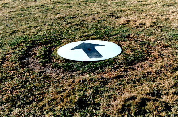
Fig. A3. Scorch marks left on the
ground by landed UFOs
(Upper drawings) The dependence of the shape of landing site from
the height (hx, hy, hz) at which a single magnocraft hovers. The
illustrated shapes are typical for the following situation: the base
of a single vehicle is parallel to the surface of the ground, the
axis of the main propulsor is parallel to the central axis of the
vehicle, the position of the vehicle is upright, the magnetic
circuits are spinning. When any of the above factors change, the
shape of the landing site must also alter.
-
The shape of marks formed when the
height of hovering (hx) is greater than the critical span (hc)
at which the central column of main magnetic circuits (M)
separates into two loops. The upper part shows vehicle’s
magnetic circuits: central ©, main (M), and side (S). In the
lower part of the drawing the landing site scorched by these
circuits is shown. The distinct features of this site are two
concentric rings: the outer having the maximal diameter “do”
close to the nominal diameter “d” of the vehicle, and the inner
ring with the inner diameter “di”. The corrective equation for
this landing takes the form: d=do+di.
-
A mark scorched when the vehicle
hovers at height “hy” which is smaller than “hc” but larger than
the span “hs” of the side circuits. Note the outer ring of
diameter “do” (smaller than “d”) and a patch with the intensive
centre “da”.
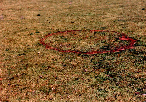
-
Concentric rings scorched when a
given vehicle landed on its base, or hovered at a height “hz”
smaller that span “hs” of side circuits. In this case the inner
diameter of the outer ring is equal to the outer diameter D of
the vehicle.
(Lower photographs) Photographs of landing sites formed in New
Zealand by single UFOs, which illustrate all three main cases
presented in the upper drawings.
-
A K3 type UFO landing with two
concentric rings formed in 1988 in a silage paddock of Mr Geoff
Genmell (Horse Range Rd, No 2 R.D., Palmerston, New Zealand).
The diameters are do=2.1 and di=1 [m] (thus d=do+di=3.1
[meters]).
-
A K3 type UFO landing found in the
morning, on 6 December 1978, in a paddock of Mr Barry Badman
(Wrights Bush, No 8 RD, Invercargill, New Zealand). Note the
central patch scorched by the column of the field from the main
propulsor displaced to the right of the site (in reality towards
the magnetic south direction). It touches the outer ring.
-
A fragment of the paddock with over
a hundred of UFO landings. It belongs to G. Derek George (Waimarie,
Amberley, North Canterbury, New Zealand). Here UFOs landed on
their bases to take on the deck sheep grazing at that paddock.
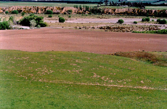
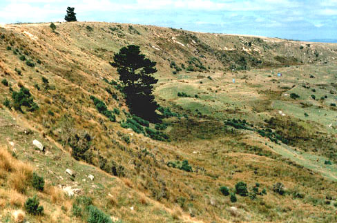
Fig. A4. The Tapanui Crater
This huge explosion site measuring
900x600x130 metres, was formed on 19 June 1178 in the Otago province
of New Zealand. It is located on the private property of Mr Rex L.
Hellier (Pukerau, 1 R.D., Gore, New Zealand; tel: -64 (3)
205-38-64). The evidence suggests that it was produced when around
seven UFOs type K6 (time vehicles), stacked together into a
cigar-shaped configuration (similar to the configuration shown in
part #1 of Figure A2), exploded top-to-bottom close to the ground
with a yield of over 70 megatons of magnetic and telekinetic energy.
The Tapanui Crater is the second
location (after the site of the famous Tunguska Blast of 1908 in
Central Siberia, USSR) identified so-far where UFOs have exploded.
-
(top) The eastern section of the
Tapanui Crater, photographed from the northern end. The curved
slope in the top left of this photograph represents the Crater’s
most spectacular side, as the western edge rises only a few
meters from the lower part of Pukeruau hill. A fully-grown pine
tree visible in the centre of this frame well illustrates the
slope’s maximal depth. Another, more distant pine tree visible
on the top of Pukeruau hill, provides an identification
land-mark for people visiting this Crater.
-
(bottom-left) Shape of the Tapanui
Crater (coordinates: 46°04’S, 169°09’E). The similarities
existing between the configuration of this crater and the
Tunguska blast site certify that the origin of both sites is
analogous, i.e. from a powerful near-ground (aerial) explosion
of several UFO vehicles stacked into a cigar-shaped flying
configuration. Notice the evident correspondence (labelled 1 to
5) in:
-
the relationship between the
apical angle of triangular entries to both sites and their
distance from the nearest magnetic pole of Earth (i.e. at
the moment of explosion the Tapanui Crater was located much
closer to the magnetic pole then the Tunguska Site, thus its
apical angle is also much wider),
-
the manner explosion shockwaves
entered the ground,
-
the breaking points of the
explosion shockwaves (which in Tunguska swirled tree trunks,
whereas in Tapanui formed large sand dunes),
-
the location of the centre of
explosions and the paths followed priori by both UFO
vehicles,
-
magnetic meridian orientation of
the sites, etc. Symbols: SG/NG - geographic south-north
direction, SM/NM - magnetic south-north direction.
-
(bottom-right) Shape of the Tunguska
blast site (coordinates 60°55’N, 101°57’E) charted in 1958 (the
1958 Tunguska chart outlines only the area of total taiga
destruction, while later maps also areas of sporadically fallen
trees). Symbols: O - centre of the explosion, F - range of
scorched trees, P - path followed by the UFO vehicle prior to
the explosion, as reported by eye witnesses, L - range of trees
felled by the shockwaves of the explosion (their trunks point at
the centre of the explosion).
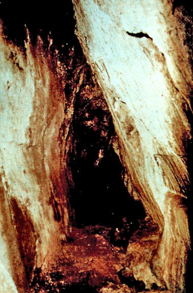
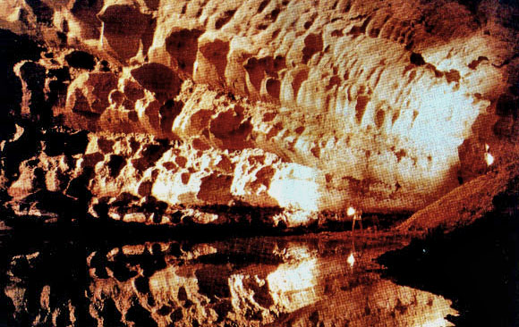
Fig. A5. Examples of
underground tunnels evaporated in rocks by UFOs
Note that large caves evaporated like
these tunnels inside of lone, landscape dominating hills are used by
our cosmic parasites even today as their underground bases for
hiding UFO vehicles, for resting, and for carrying all more labour
consuming abductions from the area dominated by these hills.
-
The Cocklebiddy Cave on the
Nullarbor Plain in Western Australia. So far about 6 kilometres
of this straight, elliptical tunnel, directed exactly
south-north, have been investigated, in spite that the most of
this length is flooded with water. Colour photographs are
published in the Australian magazine People, December 5, 1983,
pages 8 to 10.
-
Photograph of around one third of
length of the Deer Cave from the Mulu National Park in Northern
Borneo. This tunnel was evaporated by UFOs type K8. Shown is the
southern entrance currently used by tourists. The ceiling of
Deer Cave towers around 120 meters above the apparent floor.
-
A triangular, east-west oriented,
magnetized tunnel hundreds of kilometres long, discovered in the
Province of Morona-Santiago of Ecuador by Juan Moricz in June
1965. The above photograph is reproduced by the kind permission
of Erich von Däniken, from his book “In Search of Ancient Gods”
(Souvenir Press, England, 1973, ISBN 0-285-62134-3, page 341).

-
Principles involved in the formation
of such tunnels, explained by the Theory of the Magnocraft and
illustrated as if the ground were transparent. The final shape
of these tunnels (i.e. elliptical or triangular) results from
the requirement that the base of a saucer-shaped vehicle must
all times remain perpendicular to the force lines of the local
magnetic field.
-
A the evaporation of the tunnel
by the spinning plasma cloud from magnocraft magnetic whirl.
It cuts the hard rock like a huge circular saw. Symbols: 1 -
the magnocraft, 2 - the whirling disk of vehicle’s magnetic
circuits, 3 -the evaporated rock decompressing itself along
the tunnel, 4 - the rock rubble which lies at the bottom of
the tunnel.
-
A breach formed by the highly
compressed vapours expanding to the surface.
Symbols: 5 -the dispersed droplets of evaporated rock, 6
-the crack in the native rock formed by highly compresses
gases which push towards the surface.
-
Elliptical-shaped tunnel
produced by a magnocraft flying in a north-south direction.
The shape of this tunnel results from the circumferential
cross-section of the discoidal vehicle which evaporated it.
-
Triangular-shaped tunnel formed
during magnocraft flights in an east-west direction.

The shape of this tunnel results
from the axial cross-section of the discoidal vehicle which
evaporated it. Symbols: 7 - the smooth, glossy walls with
bubbles, 8 - rough and craggy apparent floor surface, 9 porous
“stony bridge” which covers the rock rubble, 10 - rubble of
native rocks which buries the true floor of the tunnel, 11 -
water that accumulates under the apparent floor, 12- the true
floor of the tunnel, 13 - range of thermal and magnetic changes
of the rock, I - inclination angle of the Earth’s magnetic field
(which defines the slanting of the magnocraft during flight).
Fig. B1. The imprint of human foot
which is around 550 million year-old
It was found west from a small township
Delta in Utah state of the USA. In 1968 the late Bill (William)
Meister was hunting for “trilobite” fossils. Widely known in the USA
deposits of these fossils are located west from this Delta township.
When he split layers of rocks in search of these fossils he almost
got petrified from a shock - in one of layers he encountered the
imprint of a human sole. This shoe even had a heel.
The imprint shown here was examined by
Mr Evan Hansen (HC 76 Box 258, Beryl, Utah 84714, USA). Hansen was a
person specially qualified for this research, because 11 years of
his life he spend as a shoe repairer in a shoe repairing shop, while
for 7 years was a manager of this shop. According to his words, this
imprint tells its own story. Without any doubt it is an imprint of a
human shoe. Whoever made it was the same human as is every person
who today is walking on our planet.
On the basis of his experience Mr Hansen
guarantees chances are zero that this imprint is anything other then
the imprint of a human shoe.
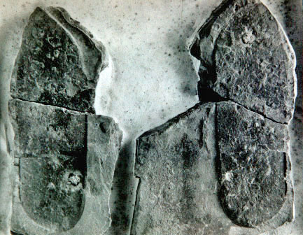
According to the analysis of Mr Hansen,
the imprint shows the right leg. This is obvious from a metatarsal
bulge at the base of the big toe. Also the heel is worn at the outer
edge, exactly the same as modern humans firstly wear their heel on
the outer edge. The owner of this shoe was builded the same as Mr
Hansen (168 cm tall?), as the shoe is 10¼ inches long (26 cm), its
sole is 3½ inches wide (9 cm), while the heel is 3 inches wide (7.5
cm) and ¼ inches thick (6 mm).
The mud cracked on toes when the wearer
of this shoe pushed it backwards to made a next step. In turn around
the heel the mud was tired and lifted after it stack to the shoe.
During the formation of this footprint its heel stepped on one of
first trilobites -i.e. creatures that most probably were then farmed
on Earth and inspected by the owner of this shoe. After being
stepped on, the trilobite curl up in protection, in a manner as
modern bugs would curl if injured. Other trilobite was pushed in mud
around toes.
Trilobite lived in the mid-Cambrian era, that means around 550
millions years ago in conventional dating. They were used to life in
very hostile environmental conditions in which other organisms were
not able to survive. Therefore trilobite are the first organisms on
Earth which form permanent remains. In layers which precede this
period, only bacteria, algas, and other low forms of life could be
found.
Therefore the imprint of a human shoe is
made in the oldest Earth rock which still contains the permanent
remains of living organisms - in this case trilobite. This in turn
provides a conclusive proof to the history from subsection B2 that
life on Earth was artificially replenished by cosmic farmers who
also farm us. It also proves that the civilization which planted us
on Earth is at least 550 millions years more developed then us, and
that so long ago it already mastered interstellar travel.
Bill Meister died in 1980s. The original place of finding this shoe
imprint was carefully hidden by him (probably in the effect of a
telepathic suggestion from UFOs), while the location of this place
was recorded on the film in which his wife indicates with her finger
the exact location of the imprint on the background of recognisable
landscape (this photograph is already lost). The ideas was that this
location could be found if a scientific expedition is ever organized
(further old human imprints still should be present in this place).
In 1999 Mrs Meister donated the imprint
to “Creation Research Museum”, P.O. Box 309, Glen Rose, Texas
76043-0309, USA (located at: 3102 F.M. 205, Glen Rose); Web site: <http//www.creationevidence.org>.
Let us hope that UFOnauts do not manage to destroy it silently, as
they have done it with other evidence on their occupation of Earth.
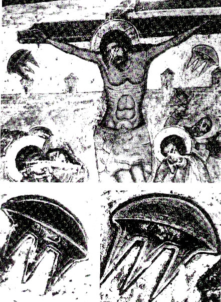
Fig. B2. An old church painting which
seems to suggest that the Crucifixion of Jesus was supervised
by UFO vehicles
This particular painting originates from
the Orthodox cathedral Sweti Cchoweli in Mcchecia -the former
capitol of Georgia (Gruzja). It was painted around 1650 by an
anonymous artist. It is reproduced on Figures 60 to 62, and
described on page 158, of the book [1FigB2] by Walter-Jörg Langbein,
entitled “Syndrom Sfinksa” (the original title: “Das Sphinx-Syndrom.
Die Rückkehr der Astronautengötter”) published in Poland, Warszawa
1997, by Wydawnictwo Prokop, ISBN 83-86096-32-2, pb, 190 pages.
The picture is representative to the
increasing body of evidence that all vital events on Earth,
including important religious events, were at least supervised, if
not caused, by our cosmic parasites.
for more information,
'click' above image
Therefore UFO vehicles were observed not
only during important battles, catastrophes, and social unrest
occasions, but also on numerous religious occasions. An excellent
selection of around 12 church paintings which captured UFO vehicles,
is presented in the article [2FigB2] by Daniela Giordano “Gothic
Discs & Renaissaucers” published in “Fate”, September 1999 issue,
pages 26 to 31. Note that on the painting shown above, the
enlargement of both UFO vehicles presented on lower Figures 61 and
62 reveals the faces of our cosmic parasites who carefully watch the
Crucifixion of Jesus.
It should be noted that these two UFO vehicles illustrated on the
above painting actually are a traditional feature in many icons from
orthodox churches that depict the Crucifixion of Jesus. For example,
near the small New Zealand town named Masterton there is the only
Greek Orthodox Church of that country, constructed around the year
1980. Richly painted walls of this church, amongst others, include
also the scene from Crucifixion of Jesus. This scene also shows
stylised UFO vehicles very similar to these illustrated above.
Fig. C1. The little white being with
blue eyes shown while holding the pyramid
This illustration was prepared by
Daniela herself, on 30 March 2000. The painting illustrates the
appearance of the being whom disclosed the pyramid to Daniela. Note
the shape and size of his head when compared to proportions of
remaining parts of body, his small nose, little chin, slit mouth,
and no hair. Especially note the contented happiness that is
emanating from his face (in subsection B4 a state of permanent
happiness achievable through the moral living is called “nirvana”).
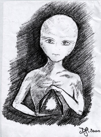
The painting also shows the exact shape
and relative size of the pyramid, as well as the manner it was held
by the being. The colour scheme of the pyramid’s surface, as well as
shadows and illustration of walls’ transparency, is conveying the
impression that Daniela got when looking at the working pyramid.
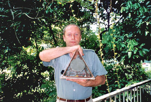
Fig. C2. A photograph of the pyramid
Shown is a prototype of this device
built in Poland, but not made operational. More details about the
purpose, operation, and theory behind this device is provided in
treatise [7], in chapter G of monographs [3] & [3/2], as well as in
chapter N of monographs [1/2] & [1/3].
Research on the prototype completed by Daniela indicated that after
an alternating current of high frequency is supplied to the device
from an external source (e.g. from a radio) the pyramid produces
some kind of telepathic signal. However, her prototype still hides
some construction errors which make it impossible to operate
according to the original specification of the giver. To eliminate
these errors, further theoretical research and physical development
needs to be carried out.
-
(Top) The side view of the whole
pyramid. The device is held by myself (Dr Jan Pajak) in a manner
similar as the little being with blue eyes held it in his hands.
During such holding the biofield of the user infiltrates through
the active space of the device. Because this bio-field carries
the thoughts of the user, it modifies with these thoughts the
state of the optical interference cavity. In turn the
modifications of this optical interference cavity are imposed
onto the electrical oscillations from the pyramid’s resonator,
thus modulating these oscillations.
After the modulation into magnetic
vibrations these thoughts are emitted into space from which they
can be intercepted by another similar device. After being
intercepted these thoughts are demodulated and superimposed on
the biofield of another user, thus appearing in his/her mind as
another set of thoughts imposed on his/her own.
-
(Bottom) The inner components of the
pyramid. The casing (hat) is visible from underneath after being
put aside on the right.
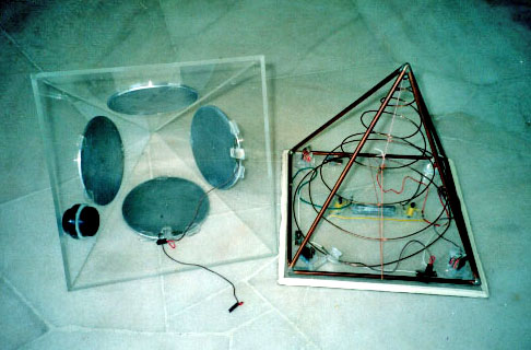
Fig. C3. The general shape, design, and
main components of the pyramid
This illustration is prepared as if all
the elements were transparent, i.e. through subsequent components
the elements, shapes, and connections placed behind them are
visible. It represents a repetition of Figure N2 from monographs
[1/3] and [1/2], and Figure 1 from treatise [7].
This device is shaped as a pyramid of around 27.5 [cm] high. Its
wiring and main components are hermetically enclosed inside a
pyramidal casing made of perspex or glass. The casing hosts: a
copper frame (F) shaped like a pyramid and aligning each corner of
the casing, a conical coil © also made of a copper wire, four
aluminium disks (D1), (D2), (D3), (D4) attached to the side walls of
the pyramidal casing - one of them (D1) should have a small hole in
the centre, quartz crystal (Q) placed at ¼ of the height, phial (T)
placed in the centre of the base, two inductors (I1) and (I2), and
four cascades of mirrors (M1), (M2), (M3), (M4) placed in four
corners of the base. All these components should not touch each
other, although they should be electrically connected together
according to the original instruction.
Their electrical properties should
fulfil the condition of “harmonic” proportions.

The phial (T) should be half filled with
ordinary kitchen salt, half with mercury. It is recommended that it
should work under a vacuum. Both inductors (I1) and (I2) are made of
small bar magnets with copper wiring tightly winded around them.
Each cascade of mirrors (M) is made of three small mirrors of
descending heights. The copper frame (F) is simply eight pieces of
copper wire joined together so that they form the shape of a
pyramid. It is recommended that the whole pyramid should be under a
vacuum.
Fig. D1. The electrical diagram which
illustrates the basic circuits and connections existing in the
pyramid
It is reproduced from Figure N3 of
monograph [1/3]. The continuous lines indicate the connections that
were described to Daniela in the original disclosure. The broken
lines indicate electrical connections which were not included in the
original disclosure, but the existence of which is explained by
theories described in chapter D of this treatise (chapter D explains
the phenomena, principles, and basic circuits involved in the
pyramid’s operation).
The below diagram illustrates my
knowledge about the operation of this device at the time of writing
this treatise (the further theoretical research which I continually
carry out, combined with experiments which hopefully will be
inspired by this treatise and may be completed by readers, in future
may introduce some improvements to this diagram).
Names of subsequent components of this
pyramid are reflecting the use of this device as a telepathyser. The
corresponding names of the same components for the operation of the
pyramid as a telekinetic battery are explained in subsection D2.4.
The pyramid is composed of the following main circuits and
individual components: (1) receiving antenna for telepathic waves.
It is composed of the quartz crystal (Q) placed in the focal point
of the telepathic resonance cavity that is formed from four
aluminium disks (D1, D2, ... D4). (2)
The modulating and demodulating circuit
(resonator - R). It is composed of such components as inductors (I1)
and (I2), a glowing tube (T), and a vacuum capacitor. The capacitor
is formed out of two types of “plates” (which differ in shapes),
separated from each other with a layer of vacuum (or air). The first
of these “plates” is formed from four aluminium disks (D1, D2, ...
D4) connected together.
The second “plate” of the capacitor is
formed from a conical coil © and a frame (F) connected to it. In
order to increase the communicativeness of this diagram, the
resonator circuit is marked with a dotted line ®. (3) The optical
interference chamber/cavity which functions as an “inouter” for
thoughts. It is composed of: a glowing tube (T) and not shown here
four cascades of mirrors (M) which cooperate with this tube. (4)
Emitting antenna which forms the telepathic waves and sends them
throughout counter-world. It has a shape of a conical coil ©.
Fig. D2. A revealing device. It
represents a simplified, self-defense version of telepathic
telescopes
Such devices, if completed, would enable
us to see our cosmic parasites which so-far successfully were hiding
from our sight by entering a state of telekinetic flickering. More
thoroughly the design of this device is described in treatise [7B].
A state of telekinetic flickering is accomplished by switching on a
sequence of fast pulses of the telekinetic field. Each such a pulse
is turning the object that is wrapped into this field into a
transparent energy pattern or cloud. But between these pulses the
object remains material and visible. Therefore, if such a flickering
is fast enough, the object becomes unnoticeable for our eyes,
similarly as in our motion pictures the flickering of individual
frames becomes invisible for us. But each pulse of the telekinetic
field can be intercepted by the device showed here, and revealed as
a glowing shape. Therefore the revealing device illustrated here
allows us to see normally invisible UFOnauts and their vehicles.
They appear as glowing figures at the
device’s electromagnetic screen (s).
As this is the case with optical
telescopes, also the revealing devices are composed of a main tube
(t), on which all other components are to be assembled. At the
frontal part of this tube a focusing magnetic lens (f) is assembled.
At the rear part of the same tube the viewing magnetic lens (v) is
assembled. In a simplified, self-defence version of the telepathic
telescopes called here “revealing devices”, such lenses (f) and (v)
are simply permanent magnets (or permanent electromagnets which use
DC).
In centre of the tube an electromagnetic
screen (s) is formed - see the dotted plane extending across the
tube (t). This screen is composed of a collision surface and the
athwart electrostatic field. The collision surface (s) is formed by
the two magnetic fields bumping into each other with their magnetic
poles (O) which represent an “outlet” for flow of counter-matter
(for the notation of magnetic polarity used by present physicists:
O=N).
The athwart electrostatic field which is
spreading from two thin electrodes (e) extending along the
peripherals of the collision surface and placed at the opposite side
of the tube (t). The whole interior of the tube must be filled up
with an extraction glow generating substance (g).
Back
to Contents
Appendixes
Appendix Z1
List of illustrations of the treatise [7/2] “Pyramid of thoughts”
(ISBN 0-9583727-1-3)
Because copies of this treatise [7/2] are to be available via
Internet, where the inclusion of illustrations may pose a technical
problem, in this listing of illustrations additional information is
provided which indicates which of the publications listed i chapter
G also contains a given Figure (most of publications listed in
chapter G was supplied to the National Library of Poland, to all
libraries of province capitols in Poland, and also to the main
libraries of almost all higher education institutions in Poland, not
mentioning similar libraries in New Zealand and in several other
countries outside Poland).
For example the symbol [1/3]-F1 means
that a give illustration is also included into the monograph [1/3]
as Figure F1. The use of symbol ~ indicates either an older version
of the same illustration, or illustration very similar, while the
use of symbol ¨ indicates a colour print of a given photograph. Note
that in the following pairs of monographs very similar illustrations
were used: [1/2] & [1/3], [3] & [3/2], [5] & [5/2], [5/3] & [5/4],
[6] & [6/2]. Also the Polish and other language versions of the same
publications have identical illustrations, e.g.: [5/2] & [5/2E], or
[7], [7E] & [7I].
Treatise [7/2] includes 29 illustrations, which in the printed
versions of this treatise are arranged into 12 Figures, a title
page, and 2 “about the authors” pages. In Internet each of these
illustrations is available as a separate item. Symbols assigned to
individual illustrations/items reflect their location on a given
Figure. Thus illustrations the symbol of which includes letter “H”
are placed in the higher row of a Figure, while illustrations with
letter “L” are placed in the lower row of a Figure. Within a given
row, symbols “l, m, r” mean the location on left, in the middle, or
on right.
In turn symbols “a, b, c”, or “1, 2, 3,
4”, indicate a writing-type order within a given Figure.
-
Fig. A1. The smallest Magnocraft -
type K3. [4B]-B1, [5/2]-19, [5/4]-G2, [1/3]~F1, [6/2]-10,
-
(A1a) General design and
components of K3 type Magnocraft. [1/3]-F1, [1E]-B1, [1I]B1,
[3/2]~H1,
-
(A1b) Side view of the smallest
magnecraft type K3. [1/3]-F1, [1E]-G4, [1I]-G4, [5/4]-G2,
-
(A1c) Twin-chamber capsule
composed of two oscillatory chambers. [1/3]-C5, [1E]-F4,
[1I]-F4, [2]C4, [3/2]-F5,
-
Fig. A2. Flying arrangements formed
by magnocraft. [1E]-G6, [1I]-G6, [2]-D3, [3/2]-H3, [5/3]-F5,
[6/2]-12, [4B]-B2,
-
Fig. A3. Scorch marks left on the
ground by landed UFOs.
-
(A3H) Connection between a
vehicle’s height and a shape of landing site. [1/3]-F33,
[1I]~G38, [5/2]-23, [5/3]-F3,
-
(A3L) Photographs of landing
sites scorched by single UFOs. [1/3]-P1, [5/2]~33, [5/3]~G9,
-
(A3Ll) Two concentric rings.
[1/3]-P1, [1E]-M7/H, [1I]-K1, [5/2]-33ª, [5/3]-G9,
[5/4]-H9a,
-
(A3Lm) A ring with central
scorching. [1/3]-P1, [1E]-M2/H, [5/2]-33b, [5/3]-G9,
[5/4]-H9b,
-
(A3Lr) A ring with a flange.
[1/3]-P1, [5/2]-33c, [5/3]-G9, [5/4]H9c,
-
Fig. A4. The Tapanui crater where
around 7 UFO vehicles exploded in 1178 AD. [1/3]-P4,
-
(A4H) A photograph of the
Tapanui crater’s eastern slope. [1/3]-P4, [1E]-M19d,
[1I]¨K4/L, [5/2]2, [5/3]-A2, [5/4]-A2,
-
(A4L) Comparison of similarities
between Tapanui and Tunguska. [1/3]-P5, [1E]-M30, [5/2]-8,
[5/3]-C6, [5/4]-C6
-
Fig. A5. Examples of underground
tunnels evaporated in rocks by UFOs. [1/3]-P6, [5/2]~32,
[6/2]~21, (#1-#3) Photos of tunnels evaporated in rocks by UFOs.
[1/3]-P6, [4B]-B4,
-
(A5_1) Cocklebiddy Cave,
Australia. [1E]-M18, [1I]¨K3/1, [5/2]-32/2, [5/3]-G8,
[6/2]-21/2, [4B]-B4b,
-
(A5_2) Deer Cave, Borneo,
Malaysia. [1/3]-P6, [4B]-B4/L,
-
(A5_3) Tunnel Morona-Santiago,
Ecuador. [1E]-M17, [1I]¨K3/2ª, [5/2]-32/1, [5/3]-G8,
[6/2]-21/1, [4B]-B4a,
-
(A5_4) Principles of formation
of underground tunnels by UFOs. [1/3]-F31, [4B]-B3,
[1E]~G36, [1I]~G36,
-
Fig. B1. The 550 million year-old
imprint of human foot. [1/3]-O32,
-
Fig. B2. An old church painting on
the Crucifixion supervised by UFOs. see description under Fig.
B2,
-
Fig. C1. The little white being with
blue eyes holding the pyramid. this illustration is unique for
[7/2],
-
Fig. C2. A photograph of the pyramid
described here. [1/3]-N1, [3/2]-G1, [5/3]-F8, [7]~2,
-
(C2H) Dr Jan Pajak holding the
pyramid. [1/3]-N1, [3/2]-G1, [5/3]-F8, [7]~2,
-
(C2L) A photograph of the
pyramid’s interior. [1/3]-N1, [3/2]-G1, [5/3]-F8, [7]~2,
-
Fig. C3. The internal design of the
pyramid described here. [1/3]-N2, [3/2]-G2, [7]-1,
-
Fig. D1. The electrical circuitry
(connections) of the pyramid described here. [1/3]-N3, [3/2]-G3,
Fig. D2. A revealing device. [7B]-1/H.
Independently from Figures listed above,
treatise [7/2] uses also one drawing on the front page which
represents a repetition of illustration from Fig. C1, and also
includes passport-type photographs of both authors included into
descriptions from chapter H “About Authors”.
Back to
Contents
|