Chapter Five
The Mother of All Underground
Tunnels?
In UFOlogy, stories of secret, deep-underground tunnel systems, and the
hi-tech tunnel boring machines that make them, are often heard in connection
with sensational stories of secret, underground bases that are jointly
"manned" (is that the right word?) by those pesky aliens known as the
"Little Greys" and covert elements of the military-industrial complex.
I
don't know whether the
Little Greys are real or not. Nor do I know whether
the alleged tunnel systems are real or not.
But, I do know that the United States military had extensive plans in the
1980s to construct a very deep, hundreds-of-miles-long, underground tunnel
system somewhere in the western United States.
And in 1968 The Office of High Speed Ground Transportation of the United
States Department of Transportation (DOT) drew up plans for a very deep
underground tunnel system in the Northeast. This system was to have run
between Washington, DC and Boston, Massachusetts. This chapter explores both
the military and the DOT tunnel system plans.
Before presenting the documentation on these projects, I'd like to say that
I don't reject out of hand the possibility of secret, underground tunnel
systems. Far from it. In fact, based on much research and many
conversations, I think there may very easily be secret tunnel
systems, deep underground, that may be quite lengthy. But since I cannot
rigorously document their existence, I will restrict the discussion to a
presentation of what can be documented - U.S. government plans for deep
underground, elaborate tunnel systems.
U.S. National Committee on Tunneling Technology
- and Pentagon Plans for a Deeply Based Missile Tunnel System
In 1972 the Chairman of the Federal
Council for Science and Technology asked the Presidents of the National
Academy of Sciences and the National Academy of Engineering to establish a
U.S. National Committee on Tunneling Technology (USNC/TT).
The committee was
then formed by the Governing Board of the National Research Council.
The committee functions as the,
"United States focal agency in the field of
tunneling technology, to assess and stimulate improvements in tunneling
technology applications, and to coordinate U.S. tunneling technology
activities with those of other nations."
Its members are drawn from a wide
variety of federal, state and local government agencies; from academic
departments in universities; and from private industry, labor organizations
and consulting firms.
In 1977 the USNC/TT had the following
subcommittees:
-
Management of Major Underground
Construction Projects
-
Deep Cavity and Tunnel Support Systems
-
On Site Investigation
-
Demand Forecasting
-
Education and Training
-
Contracting Practices 1
Deep Underground Tunnel Plans
In 1981 and 1982 the USNC/TT
sponsored a special project called "Workshop on Technology for the Design
and Construction of Deep Underground Defense Facilities." 2
The project was
sponsored by the U.S. Bureau of Mines under contract no. JO 199025.
Co-sponsoring agencies with the Bureau of Mines were,
the U.S. Geological
Survey, Bureau of Reclamation, Defense Nuclear Agency, Department of the Air
Force, Department of the Army, Department of the Navy, Department of Energy,
National Science Foundation, Federal Highway Administration and the Urban
Mass Transportation Administration.
The workshop was called at the request
of the Defense Nuclear Agency to plan for the construction of a deeply based
nuclear missile system.
The moderator of the workshop was Edward J. Cording,
of the Department of Civil Engineering, University of Illinois at Urbana and
then chairman of the USNC/TT. Work groups were formed for Siting; The Use of
Existing Underground Space; Egress; Mechanical Mining; Construction
Planning; and Management, Contracting, Costing, and Personnel.
The select
roster of participants included,
-
dozens of professionals, including private
consultants and consulting firms from many states
-
public utilities such as
Pacific Gas & Electric Co.
-
universities such as Cornell, Stanford,
Pennsylvania State and the Colorado School of Mines
-
even a union (Local 147 of the
Compressed Air and Free Air Tunnel Workers)
According to reports issued by the USNC/TT in 1982, the planners assumed
that 400 miles of tunnels ranging from 2,500 to 3,500 ft. underground would
need to be constructed to connect the deep bases that would house MX nuclear
missiles.
The tunnels would be 16 ft. in diameter,
"with access shafts,
interconnecting passageways, and adits for storage, living quarters and
other needs." (An adit is either a horizontal passageway, an entrance, or an
approach).
Electric power would be obtained from either fuel cells or nuclear reactors.
Spare tunnel boring machines would also be stored in the tunnel
system. The
plan mentioned deep underground shops for the complete repair of tunnel
boring machines. There were to be special tunnel boring machines for digging
out from deep underground after a nuclear attack, so that reserve nuclear
missiles stored thousands of feet underground could be fired in retaliation.
In the event of war, the base would be sealed off and power for the
underground system of tunnels, tunnel boring machine repair shops, crew
quarters and missile nests would need to be internally generated. Boeing
Aerospace Company published the results of a study in 1984 that set forth
plans for power generation in a sealed, deep ICBM base.
After examining several options, Boeing decided that iron-chlorine fuel
cells would be the most efficient way to generate electricity. In this
power-generation scheme huge, underground tanks store liquid chlorine that
is combined with hydrogen to form hydrochloric acid (HCL).
This chemical
reaction generates electricity.
The HCL is then pumped into huge tanks
filled with small iron balls; the iron (Fe) and HCL react chemically to form
ferrous chloride (FeCl2) and release hydrogen gas, which is then pumped back
to the fuel cell to react again with the liquid chlorine, starting the whole
cycle over. Iron-chlorine fuel cells are the preferred mode of power
generation if the post-attack confinement of the base lasts for less than
four years.
If the base were to be sealed for more than four years, however, financial
cost-benefit analysis indicated that liquid-metal-cooled nuclear reactors
would be recommended over iron-chlorine fuel cells. The report does not say,
but based on other literature I have seen the liquid-metal used to cool the
liquid-metal-cooled reactors would probably be lithium.3
The USNC/TT tunnel plan called for the system to be built in the late 1980s
and early 1990s, with "mobilization" of manpower and resources beginning in
the early 1980s.
The probable tunnel boring machine (TBM) supplier for the
project indicated that it could supply,
"two machines between January and
June 1985, one machine per month between July and December 1985, two
machines per month between January and June 1986, and three to four machines
per month thereafter."
That supply schedule was predicated on using a 16 ft.
tunnel diameter. If 18 ft. were selected as the diameter, the manufacturer
was able to make available 8 to 10 second-hand TBMs that could be
reconditioned for immediate service.4
The report includes artists' conceptions of how portions of a deeply based
missile tunnel system might look (See Illustrations 22-24). Where might this
system be located, assuming it has already been built, or is now under
construction?
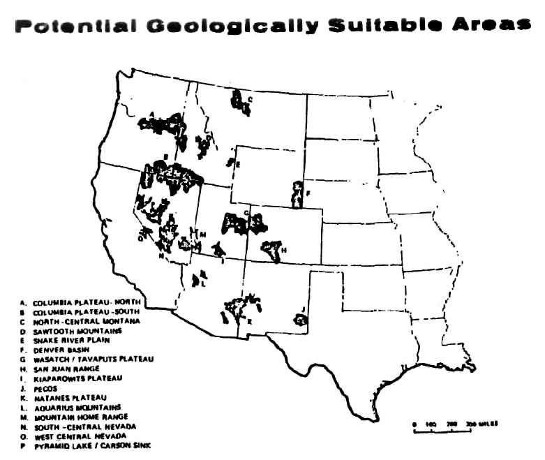
The planners assumed it would be built somewhere in the western third of the
country (See Illustration 27).
Three specific sites mentioned in the text of
the report are:
-
Forty-Mile Canyon in Nevada
-
Grand Mesa, Colorado
-
the basalt plain in the Columbia River
Basin, near Fairchild Air Force Base in the State of Washington
There are other federal documents and press
reports which explicitly discuss this deep underground tunnel system. In
August 1980, the Air Force released a detailed, two-volume study which was
prepared by the School of
Mines, in Golden, Colorado. The study is entitled, "Tunnel Boring Machine
Technology for a Deeply Based Missile System." 5
It calls for a 480 km long
(about 300 miles), deep underground tunnel system that would connect
"missile nests" 2400 ft. or more underground.
In the event of nuclear war,
the plans call for military crews to operate mechanical, tunnel boring
machines that would bore up to the surface from bases half a mile or more
underground, towing nuclear missiles behind them, which they would then fire
at the enemy (See Illustrations 25 and 26 for schematic diagrams of the
egress tunnel boring machine designs, and missile egress plans from deep
underground).
The tunnel boring machine companies mentioned in the report
are The Robbins Company, of Kent, Washington and Jarva Inc., of Solon, Ohio.
Morrison Knudsen, of Boise, Idaho (a huge company with subsidiaries in many
states) is mentioned as a construction consultant.
There are many other documents and articles that detail these plans. In 1984
The New York Times ran a front page story that described the planned,
underground missile base as something like a,
"400-mile network of subways
that would be 2,500 to 3,500 feet below the surface, probably in a desert in
the western United States." 6
In 1985 the Asian Defense Journal ran an almost
identical story.7
A highly technical 1985 document from the Air Force Geophysics Laboratory
discusses ground motion effects that a deep underground facility might
experience were it to undergo nuclear attack. In particular, it refers to an,
"underground missile base within Generic Mountain B in the ICBM Basing
Construction Planning Study." 8
Unfortunately, no specific location or layout
for the missile base is mentioned.
A 1985 report from the Army Corps of Engineers Omaha District explicitly
refers to an "ICBM deep basing construction planning study." 9
Another, 1988
report by the U.S. National Committee on Tunneling Technology and the
U.S. National Committee for Rock Mechanics discussed an underground missile
system ranging between 3,000 ft. and 8,000 ft. underground. That's right -
as much as 8,000 ft. underground.
This 1988 report mentions having the base operational as soon as possible,
"within a five-year construction schedule." Five years from 1988 is 1993. Is
such a base now operational, far below some unknown location in the United
States? Based on my research, I am not certain. However, given the rather
substantial paper trail, it is certainly within the realm of possibility
that something like it has been secretly built.
The 1988 report calls for a system with tunnels up to 20 miles long,
branching off from access shafts.
The report's conclusion states,
"The
consensus of the working groups involved in preparing this report is that
the basic technical capabilities to create complex underground facilities at
the pace and depth envisioned are available in current practice."10
A series of federal contracts for development of the deep underground
missile system were let in the mid1980s by the Air Force's Ballistic Missile
Office, at Norton Air Force Base, in California.
The contracts that were let
do not, in and of themselves, prove that the project has actually been
carried out. At the least, though, they do demonstrate that this concept
went well beyond a paper, planning stage and began to develop real, hard
technology.
United Technologies, Hamilton Standard Division, of Windsor Locks,
Connecticut was given a contract in November 1985 for "life support and
chemical/biological agent mitigation systems on the Small Intercontinental
Ballistic Missile (ICBM) Deep Basing Program." The projected completion date
for the work was February 1988. The Federal Contract No. was:
F04704-85-C-0111.11
This contract would probably have to do with supply of
pure air and water for the crew(s) of an underground base.
In December 1985, BDM of McLean, Virginia was awarded a contract to conduct
an "intercontinental ballistic missile (ICBM) deep basing communication
study." The contract was to be completed by February 1988; the Federal
Contract No. was: F04704-86-C-0045.12
In 1986 Bell Aerospace Textron was given a contract for an "ICBM deep basing
gas propelled launcher feasibility demonstration." Plans called for
completion of the contract by June 1988. The Federal Contract No. was:
F04704-86C-0100.13 The wording of the contract announcement creates the
image of a nuclear missile being ejected into flight from the mouth of a
tunnel bored to the surface from deep underground.
In 1987 Earth Technology, of San Bernardino, California was awarded a
multi-million dollar increase to a previously awarded contract, in order to
carry out what the Department of Defense rather fuzzily referred to as
"geotechnical and siting deep basing fine screening Phase I and II."14 In
ordinary language this would seem to mean that the Ballistic Missile Office
paid this company millions of dollars to do a two-phase geological and
technical study, to fine screen sites where a deep underground missile base
would be located.
The Federal Contract No. was: F0470485-C-0084.
And finally, the Robbins Company, of Kent, Washington (the tunnel boring
machine manufacturer mentioned in the Air Force Weapons Laboratory/Colorado
School of Mines two-volume report mentioned above) was awarded a contract in
1985 for "egress/excavation development and testing."15
Presumably, this
refers to excavation for egress of nuclear missiles from deep underground,
since the contract was let by the Ballistic Missile Office at Norton Air
Force Base. The Federal Contract No. was: F04704-85-C-0112.
So is there really a secret, military tunnel system? The short answer to
this question is: I am not certain.
But the documents, articles and contracts referred to above suggest it is
entirely possible that the military, working through the Ballistic Missile
Office at Norton Air Force Base, with the probable assistance of the Army
Corps of Engineers and private companies such as Robbins, Earth Technology,
and others, has secretly built an extensive, very deeply buried tunnel
system and nuclear missile complex, somewhere in the United States, perhaps
somewhere in the West.
If it has been made, this system may be, in its totality, hundreds of miles
long and thousands of feet underground. If it exists it is certainly very
well hidden. And if it exists it may very well explain either partly or
wholly the recurrent rumors in UFOlogy about a secret tunnel system in the
southwestern United States. But even if it has not been built, the extensive
plans, studies, and various contracts referred to above would be sufficient
to fuel rumors about the existence of such a tunnel system.
From the standpoint of disinformation there is another possibility: that the
military has really built a tunnel system of the sort described here, but
has tried to hide its existence under a tabloid-style cover story of alien
tunneling activities.
According to this hypothetical scenario the military
would count on the "alien" connection to be sufficiently ridiculous in the
public eye that if word of the tunnels ever surfaced in the media they could
be discounted as the fevered imaginings of daffy UFOlogists
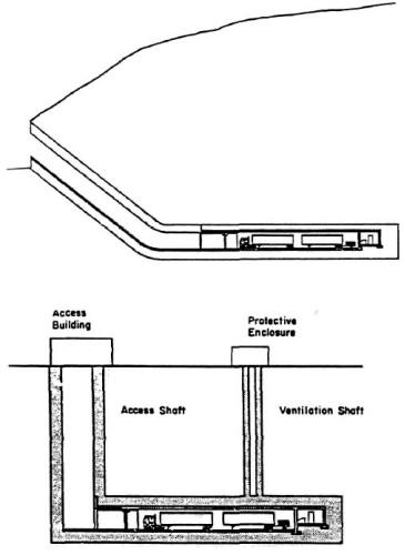
ILLUSTRATION 1
Even though hidden from public view behind layers of
high security, entrances to underground bases nevertheless can be big
enough to literally drive a truck into. Two means of approach are shown
here. Source: U.S. Army Corps of Engineers, Literature Survey of
Underground Construction Methods for Application to Hardened Facilities.
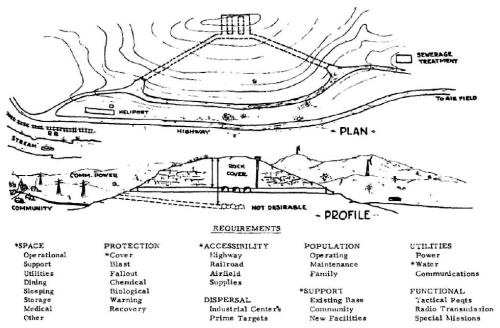
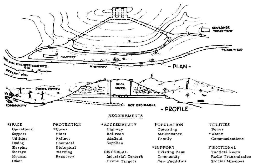
ILLUSTRATION 2
Example of Army Corps of Engineers plan for an
underground base, circa late 1950s. Notice the microwave towers for
communication and planned proximity to a community, highway, railroad
tracks and power lines. Note, too, that two entrances are preferred and
that there is a vertical shaft to the surface as well, perhaps for air.
Source: M.D. Kirkpatrick, in Protective Construction in a Nuclear Age:
Proceedings of the 2nd Protective Construction Symposium. 24-26 March
1959. Vol. I ed. J.J. O'Sullivan (New York: The Macmillan Co., 1961).

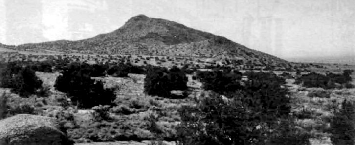
ILLUSTRATION 3
There is an underground facility beneath this ridge in
the Manzano foothills on the outskirts of Albuquerque, New Mexico. This
underground installation, begun in the late 1940s, is on Kirtland Air
Force Base. Photo by the author.
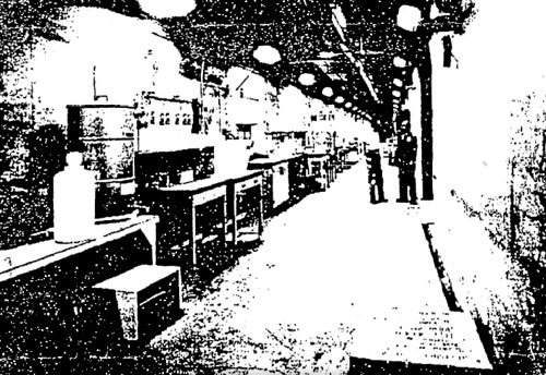
ILLUSTRATION 4
An underground chamber in the mysterious Los Alamos Lab
facility, circa 1940s. After repeated requests, the Department of Energy
released a badly blurred photostatic copy of a magazine article that
included this photograph. See Pages 27-30 for the whole story. Original
publication unknown.
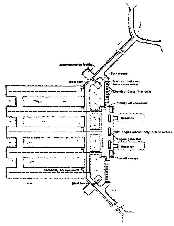
Example of underground plant arrangement

ILLUSTRATION 5
Even in the 1950s, military planning for sizeable
underground installations was in full swing. Note the decontamination
room, the chemical filter units, the blast closure valves on the fresh
air intake units, and the water reservoirs. From U.S. Army Corps of
Engineers, Design of Underground Installations in Rock: Protective
Features and Utilities.
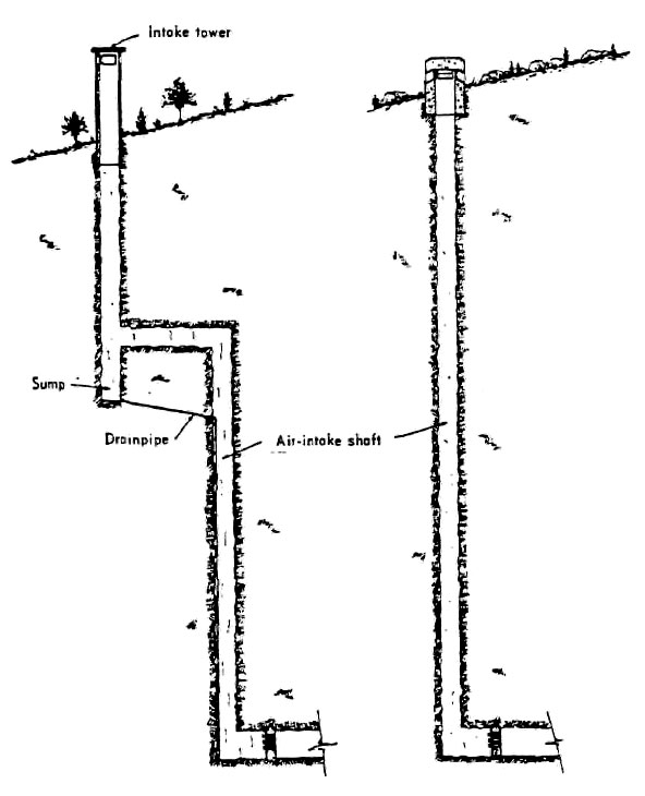
Example of air-intake shafts

ILLUSTRATION 6
Two ways of protecting the fresh air intake from above
ground, circa 1950s. From U.S. Army Corps of Engineers, Desisn of
Underground Installations in Rock: Protective Features and Utilities.
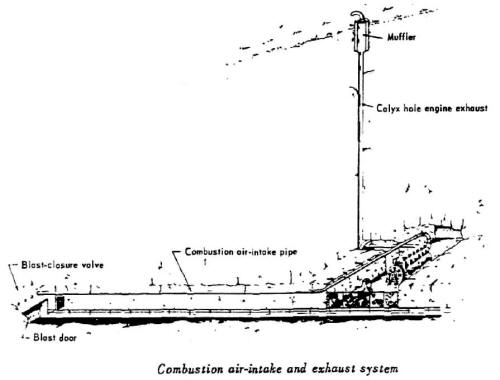
ILLUSTRATION 7
Machinery powered by internal-combustion engines
underground would use up valuable breathing air, so the military
planners in the 1950s devised a way to supply air to the machines, and
exhaust the fumes. Source: U.S. Army Corps of Engineers, Design of
Underground Installations in Rock: Protective Features and Utilities.
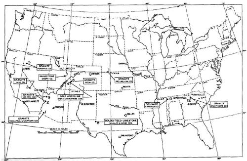
ILLUSTRATION 8
In 1964, the Army Corps of Engineers picked 12 sites
suitable for the construction of 600-ft. diameter cavities 4,000 ft.
underground, for the purpose of setting off nuclear bomb test
explosions. Source: U.S. Army Corps of Engineers, Feasibility of
Constructing Large Underground Cavities. Vol I.
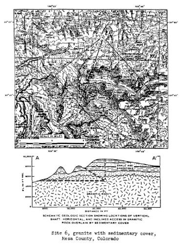
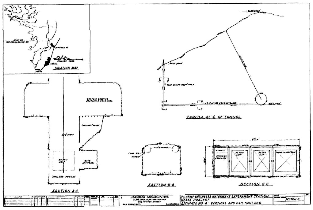
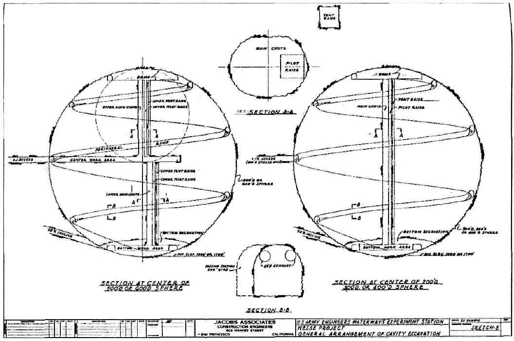
ILLUSTRATION 9
One of the sites selected by the U.S. Army Corps of
Engineers In 1964, suitable for constructing a large cavity, deep
underground, for testing nuclear bombs. Note that the horizontal option
for access takes the form of a tunnel miles long. Source: U.S. Army
Corps of Engineers, Feasibility of Constructing Large Underground
Cavities, Vol. I.
ILLUSTRATION 10
A 1964 plan from the Army Corps of Engineers to
construct a large underground cavity 4,000 feet underneath Argus Peak,
northwest of Trona, California. If built, this facility would today be
within the boundaries of the China Lake Naval Weapons Center, which has
long been rumored to be the site of a massive underground installation.
Source: U.S. Army Corps of Engineers, Feasibility of Constructing Large
Underground Cavities. Vol. III.

ILLUSTRATION 11
A beautiful piece of drafting work from the
Army Corps of Engineers, circa 1964. Was this facility, proposed for
construction within the boundaries of present-day China Lake Naval
Weapons Center, northwest of Trona, California, ever built? Source: U.S.
Army Corps of Engineers, Feasibility of Constructing Large Underground
Cavities, Vol. III.
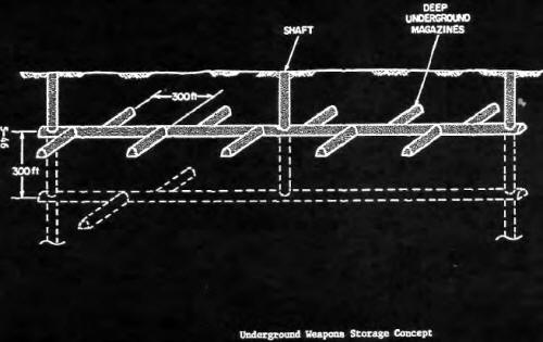
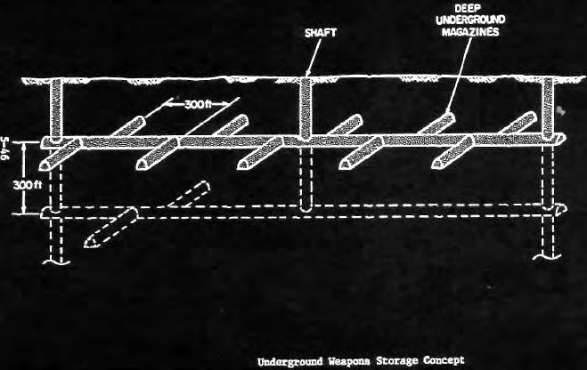
ILLUSTRATION 12
You'd think the Navy would stick to the
water, but no --they have plans to dig underground, too. Here they're
figuring out how to store and hide their weapons. Source: R. Hibbard,
et. al., Subsurface Deployment of Naval Facilities, 1972.
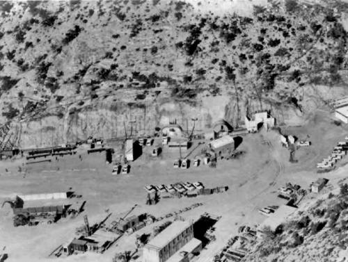
ILLUSTRATION 13
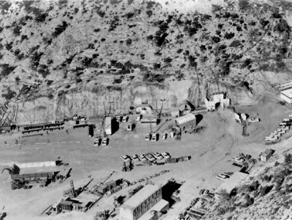
The Nevada Test Site, shown here in an official
Department of Energy photo taken in 1980, at the time of a less than
20-kiloton nuclear bomb test that took place 1,280 feet beneath Rainier
Mesa. The test, designed by the Los Alamos National Laboratory, was
conducted for the U.S. Defense Nuclear Agency. There are three
underground entrances visible; one is large enough to receive a train.
The numerous parked trucks are reminders of the large numbers of people
who work underground. They're not likely, though, to discuss their work
with you: the secrecy oaths that they sign are very intimidating.
Department of Energy photo.
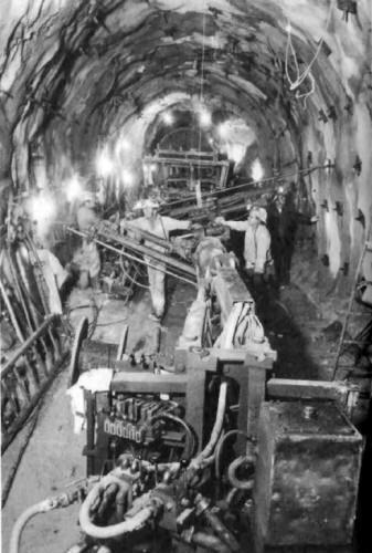
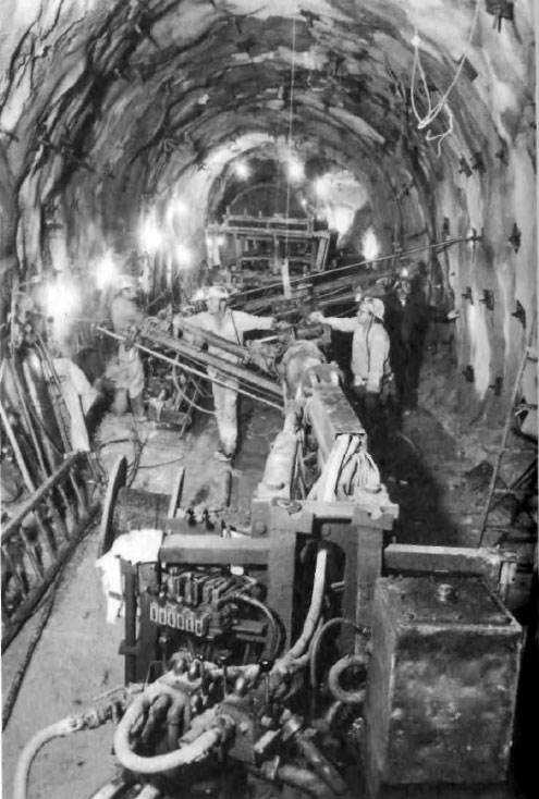
ILLUSTRATION 14
Miners at work in tunnels beneath Rainier
Mesa at the Nevada Test Site. They're stabilizing the walls with rock
bolts and epoxy so that when the nuclear explosions go off, the walls
won't crumble. Department of Energy photo.

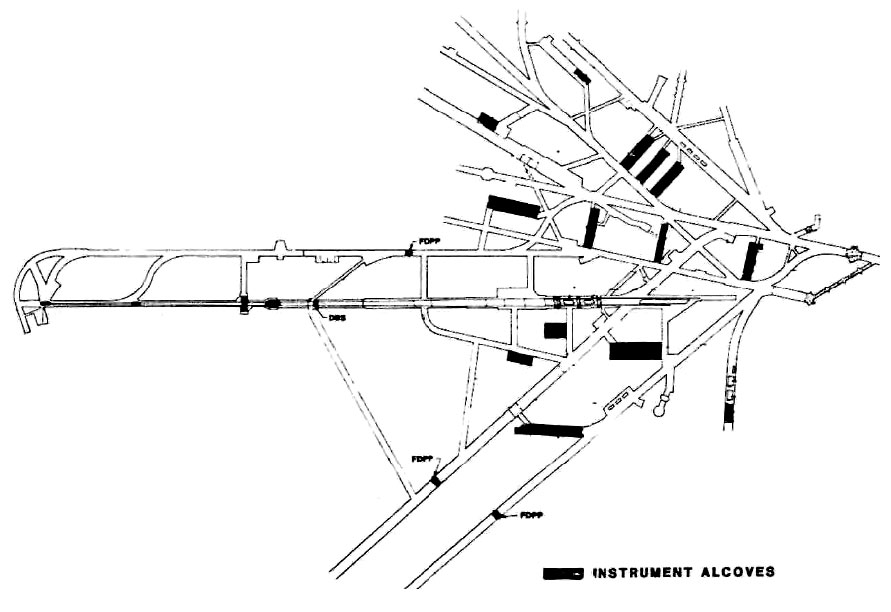
ILLUSTRATION 15
A partial map of "N" Tunnel, just one of the
many tunnel complexes at the Nevada Test Site. Most of the black boxes
are instrument alcoves. This labyrinth of passageways and tunnels -and
it's only a fragment of the whole -reveals how much time and energy has
been spent underground by just part of just one government agency at
just one site. Department of Energy photo.

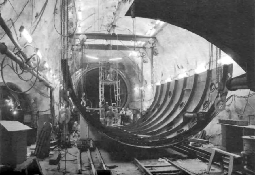
ILLUSTRATION 16
A "line-of-sight" pipe under construction
under Rainier Mesa at the Nevada Test Site. These pipes, which can be up
to 27 ft. in diameter, serve as test chambers that house monitoring
equipment. They are placed 900 to 2,000 ft. from the nuclear blast.
Defense Nuclear Agency photo.

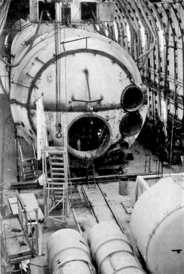
ILLUSTRATION 17
Construction of nuclear test monitoring
chambers in a tunnel under Rainier Mesa, at the Nevada Test Site.
Department of Energy photo.
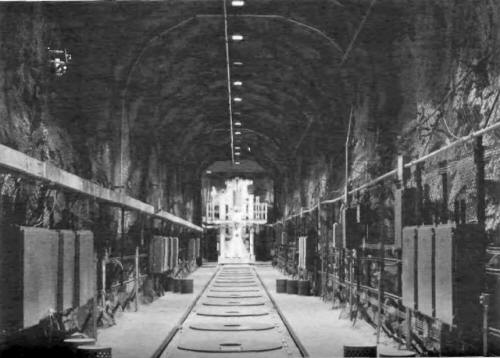
ILLUSTRATION 18
The one problem --and
it's a big one --that the nuclear industry has not yet solved is what to
do with nuclear waste. This test, run from 1980-83 at the Nevada Test
Site, evaluated the effects of storing spent reactor fuel in a granite
formation, 1,400 ft. underground. The spent nuclear fuel elements are in
steel-lined holes in the floor, capped by 5,000 lb. concrete plugs.
Department of Energy photo.
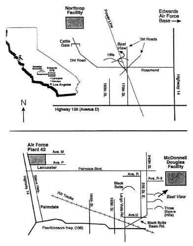
ILLUSTRATION 19
Local maps for finding the Northrop and McDonnell
Douglas facilities in the Antelope Valley of Southern California. The
Northrop facility is rumored to have as many as 42 underground levels.
These plants feature strange installations not unlike the photographs
from the Lockheed Plant in Hellendale, California (See Illustrations 20
and 21). This whole area is reported to be a great place to spot very
unconventional aircraft. This illustration reprinted with permission from
the November 1992 HUFON Report, the newsletter of the Houston UFO
Network, PO Box 942, Bellaire, TX 77402 (713)850-1352.

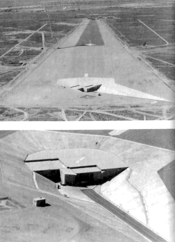
ILLUSTRATION 20
Lockheed's mysterious Hellendale, California
facility. The underground entrance (shown in close-up in lower photo) is
in foreground. Although the long paved surface would seem to be a
landing strip, it is interrupted by two huge pylons, which serve to
render this "landing strip" unusable for conventional fixed-wing
aircraft. Photos collection of the author.
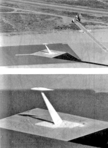
ILLUSTRATION 21
Long shot and close-up view of unknown
object on a test pylon at Lockheed's Hellendale, California facility.
The pylon can be lowered into an underground chamber until it disappears
from view (the white area around its base are doors which open and
close). Some reports say that this is a radar testing facility, and the
antenna dish bounces radar waves off test objects. Photos collection of
the author.
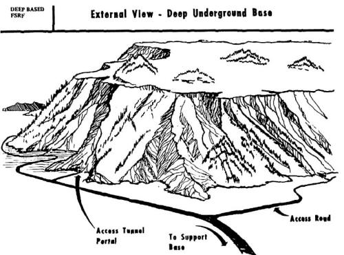
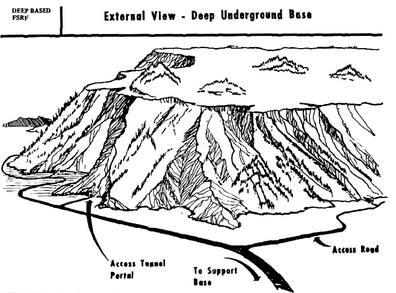
ILLUSTRATION 22
A 1982 report from the U.S. National
Committee on Tunneling Technology contained this picture of what a deep
underground base for strategic missiles would look like -from the
outside. Source: Design and Construction of Deep Underground Basing
Facilities for Strategic Missiles. Vol 2. Briefings on Systems Concepts
and Requirements. Fed. Doc No. NRC/CETS/TT-82-2.

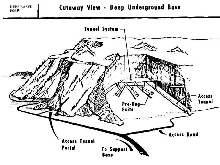
ILLUSTRATION 23
Cutaway view of a deep underground base.
Note the pre-dug exits for possible missile launchers. Source: Design
and Construction of Deep Underground Basing Facilities for Strategic
Missiles, Vol 2. Briefings on Systems Concepts and Requirements, Fed.
Doc. No. NRC/CETS/TT-82-2.
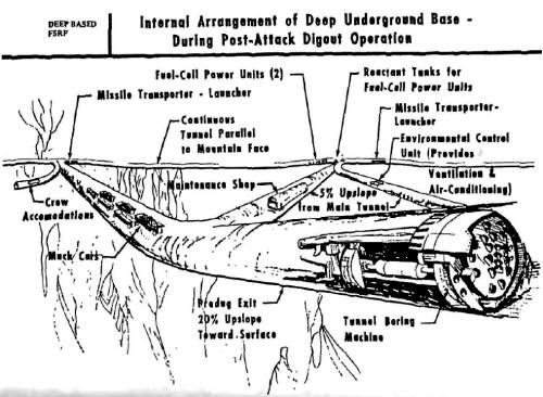
ILLUSTRATION 24
The tunnel boring machine (TBM) inside the pre-dug exit
goes into action and bores the rest of the way out from deep
underground. In this representation, the missile transporter and
launcher are in the background. Source: Design and Construction of Deep
Underground Basing Facilities for Strategic Missiles, Vol. 2, Briefings
on Systems Concepts and Requirements, Fed. Doc. No. NRC/CETS/TT-82-2.

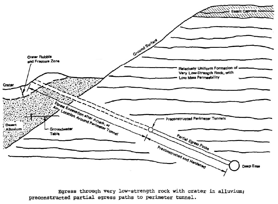
ILLUSTRATION 25
Here's a side view of the post-attack
dig-out tunnel. Source: Design and Construction of Deep Underground
Basing Facilities for Strategic Missiles. Vol. 1. Evaluation of
Technical Issues. Fed. Doc. No. NRC/CETS/TT82-1.
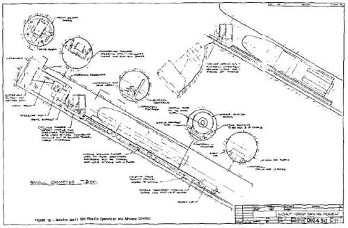
ILLUSTRATION 26
Here's a detailed schematic from the Air Force for a
combination tunnel-boring machine and nuclear missile launcher that
would be used to dig out of a deep underground missile base and fire a
missile. The deep base would be at least a half mile underground.
Source: Tunnel boring Machine Technology for a Deeply Based Missile
System. Vol 1. Pt. 1. Application Feasibility. Fed. Tech. Doc.
No.AFWLTR-79-120 (August 1980).
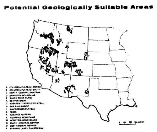
ILLUSTRATION 27
The government identified these 16 spots as
potential sites for deep underground basing facilities for strategic
nuclear missiles. Source: Design and Construction of Deep Underground
Basing Facilities for Strategic Missiles. Vol. 2. Briefings on Systems
Concepts and Requirements. Fed. Doc. No. NRC/CETS/TT-82-2.

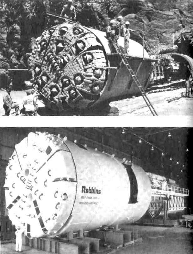
ILLUSTRATION 28
Two tunnel boring machines (TBMs) sold by
The Robbins Company. The top model was built for La Reunion irrigation
project; the bottom one for Boston Outfall. The front ends of these TBMs
chew away the rock; the structures that trail behind house the operators
and carry away the muck. Photos used with permission from The Robbins
Company.
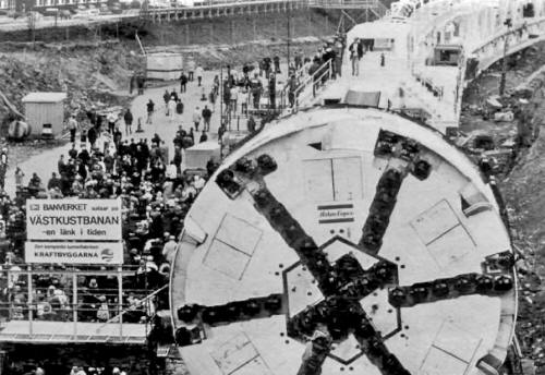
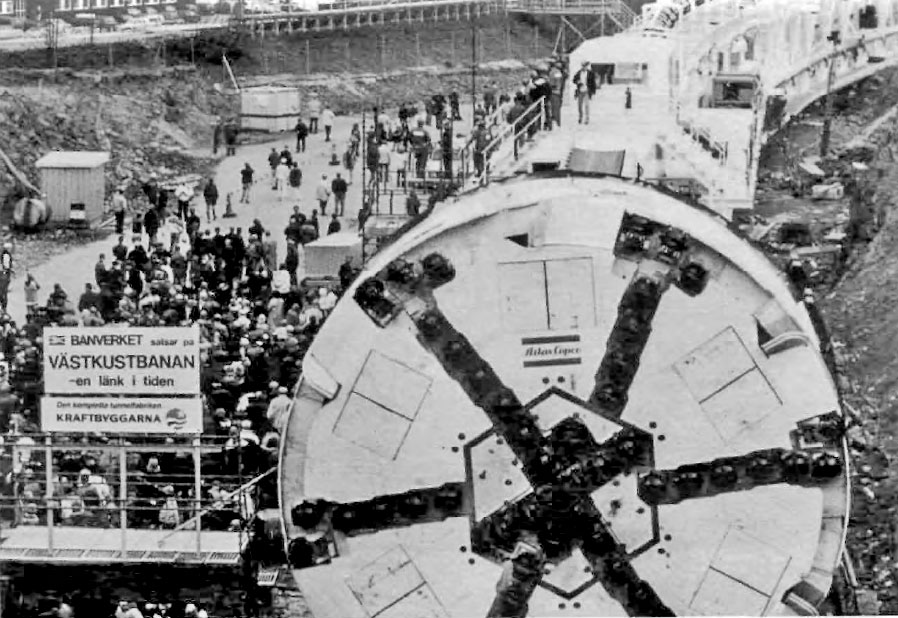
ILLUSTRATION 29
This Jarva MK27 model was used to build the
Hallandsas rail tunnel in Sweden. Photo used with permission from The
Robbins Company.

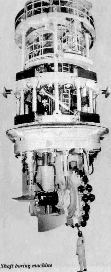
ILLUSTRATION 30
The Robbins Company manufactures huge
shaft-boring machines for excavating large vertical shafts. Photo used
with permission from The Robbins Company.
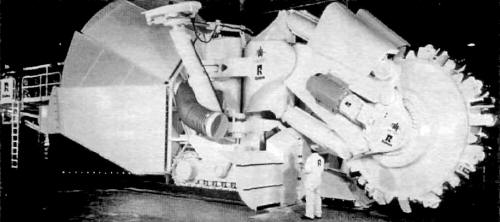
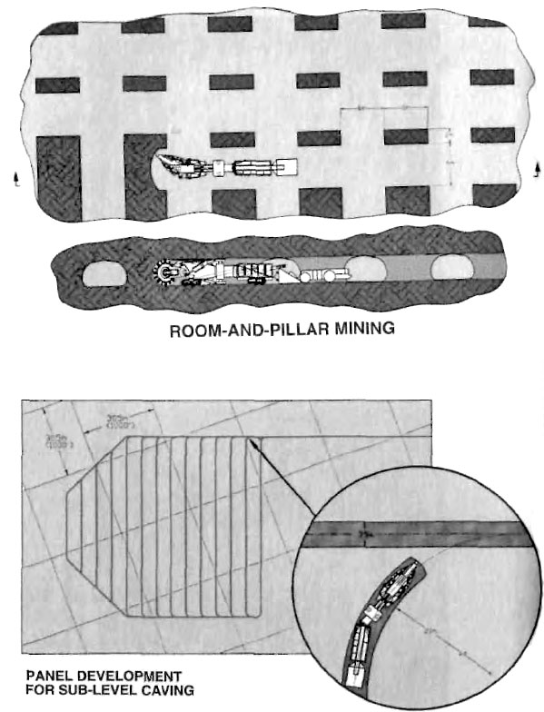
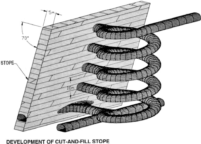
ILLUSTRATION 31
This Mobile Miner, sold by The Robbins
Company, cuts a large D-shaped tunnel. Photo used with permission from
The Robbins Company.
ILLUSTRATION 32
Depiction of a Robbins Company Mobile Miner
in action. The sales literature promises "high advance rates..." and"...
high speed tunneling..." The large area under excavation in the diagram
is amazing; each of the grids in the lower figure is 1,000 ft. on a
side. Photo used with permission from The Robbins Company.
ILLUSTRATION 33
The Mobile Miner can cut this kind of access
tunnel, which is over 15 feet wide. Photo used with permission from The
Robbins Company.

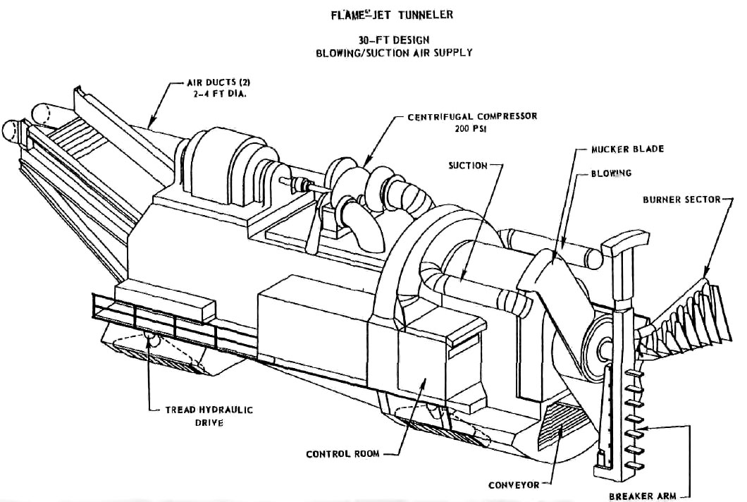
ILLUSTRATION 34
A Flame Jet Tunneler, as pictured by the
U.S. Dept. of Transportation, Office of High Speed Ground
Transportation. From Feasibility of Flame-Jet Tunneling. Volume
II-Systems Analysis and Experimental Investigations (May 1968), Fed.
Doc. No. PB-178199.
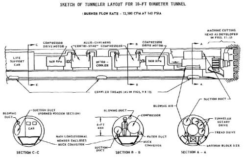
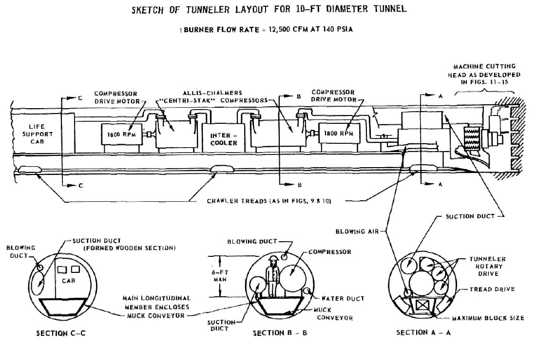
ILLUSTRATION 35
A Flame Jet Tunneler, as pictured in
cross-section by the U.S. Dept. of Transportation, Office of High Speed
Ground Transportation. From Feasibility of Flame-Jet Tunneling. Volume
II -Systems Analysis and Experimental Investigations (May 1968), Fed.
Doc. No. PB-178199.
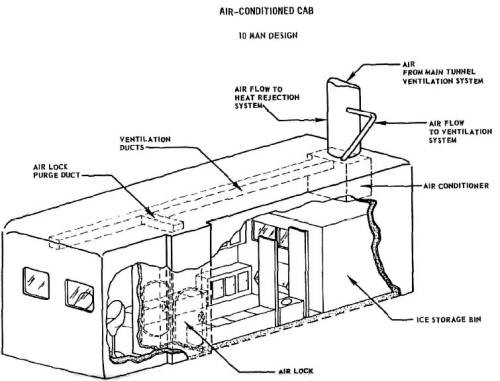
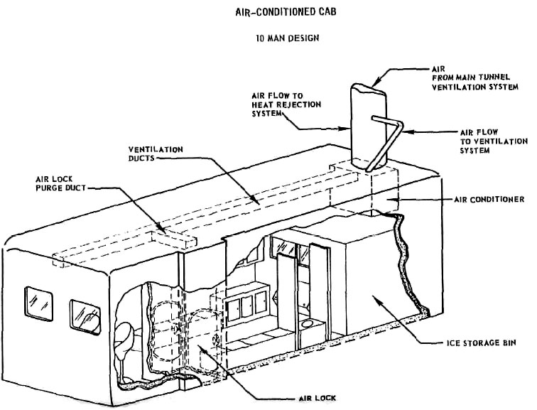
ILLUSTRATION 36
The air-conditioned cab, capacity 10 men, in a Flame
Jet Tunneler, as pictured in cross-section by the U.S. Dept. of
Transportation, Office of High Speed Ground Transportation. The heat
generated by the cutting head of this machine would be intense, judging
by the huge ice storage bin, air conditioning, and airlock. From
Feasibility of Flame-Jet Tunneling. Volume II -Systems Analysis and
Experimental Investigations (May 1968), Fed. Doc. No. PB-178199.
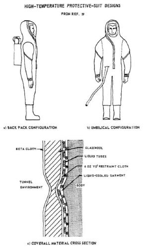
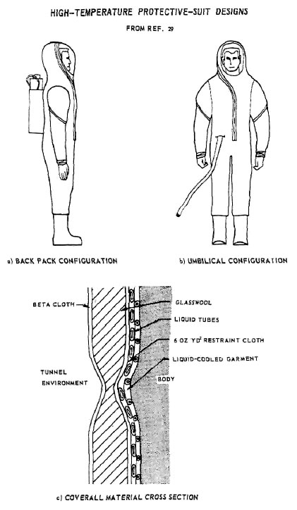
ILLUSTRATION 37
Protective suiting for the operators of the
Flame Jet Tunnelers. The umbilical cords hook up to an elaborate cooling
apparatus (not shown here). From Feasibility of Flame-Jet Tunneling,
Volume II -Systems Analysis and Experimental Investigations (May 1968),
Fed. Doc. No. PB-178199.

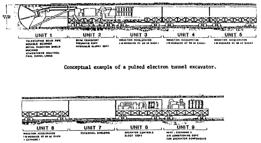
ILLUSTRATION 38
A conceptual drawing of a hard rock tunneling machine
that uses pulsed electron beams to cut the rock. To fit this
illustration on one page, the drawing was cut between Unit 5 and Unit 6;
in the original, the whole machine forms one linked set of cars. From Accelerat or Division Annual Reports, 1 July 1972-31 December 1974. Fed.
Doc. No. LBL-3835, UC-28 Particle Accelerators, TID4500-R62.

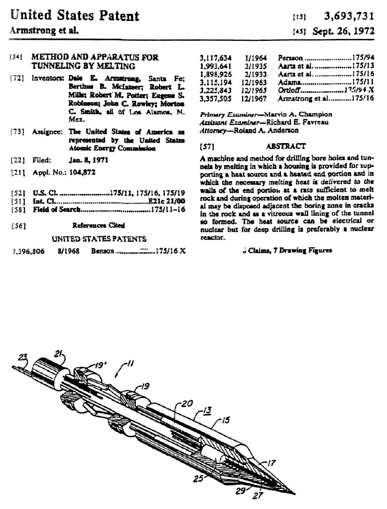
ILLUSTRATION 39
A nuclear-powered tunneling machine patented by the
United States of America, represented by the U.S. Atomic Energy
Commission. This tunneler is designed to convert the rock that it
excavates into a molten liquid, which fills cracks in the rock, bonds to
the walls of the tunnel, and leaves behind a smooth, vitreous lining.
The United States Patent Office issued the patent on 26 September 1972.
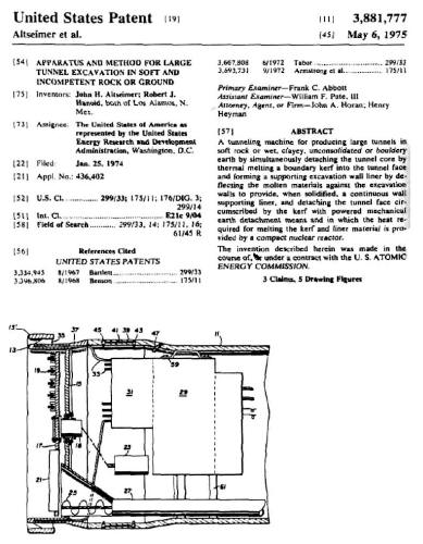
ILLUSTRATION 40
Another nuclear-powered tunneling machine patented by
the United States of America, this time represented by the U.S. Energy
Research and Development Administration. The United States Patent Office
issued the patent papers on 6 May 1975.

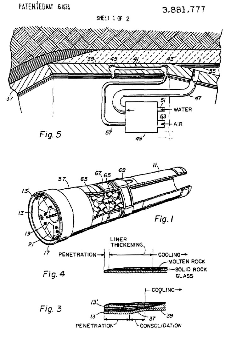
ILLUSTRATION 41
Another page of drawings from the 6 May 1975
patent for a nuclear-powered tunneling machine, granted to Los Alamos,
New Mexico inventors working for the U.S. Energy Research and
Development Administration. This machine would leave behind neat,
glass-lined tunnels.
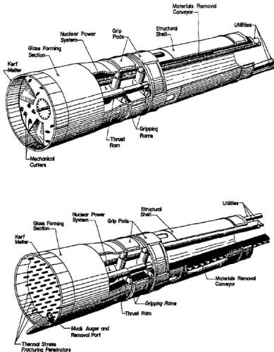
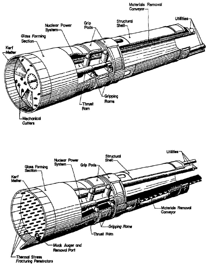
ILLUSTRATION 42
Two different types of Nuclear Subterrene
Tunnel Boring Machines. These machines are designed to melt their way
through the rock and soil, leaving behind neat, glass lined tunnels.
Source: Large Suberrene Rock-Melting Tunnel Excavation Systems: A
Preliminary Study. Fed. Doc. No. LA-5210-MS.
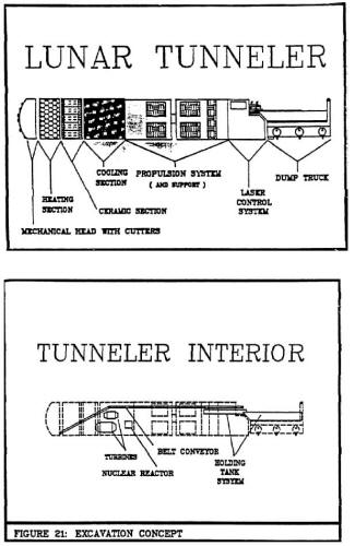
ILLUSTRATION 43
A Lunar Tunneler, as proposed in a project
funded by a grant from NASA/USRA. Reprinted with permission from
Proposal for a Lunar Tumid-boring Machine, by Allen, Cooper, Davila,
Mahendra and Tagaras, report presented to Prof. Stan Lowy, Dept. of
Aerospace Engineering, Texas A&M University (5 May 1988).
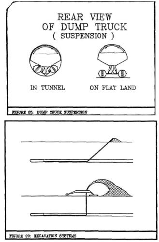
ILLUSTRATION 44
The dumping process from the Lunar Tunneler
proposal. In the bottom drawing, excavated lunar soil is sprayed into a
large pile by a movable car. Reprinted with permission from Proposal for
a Lunar Tunnel-boring Machine. by Allen, Cooper, Davila, Mahendra and
Tagaras, report presented to Prof. Stan Lowy, Dept. of Aerospace
Engineering, Texas A&M University (5 May 1988).
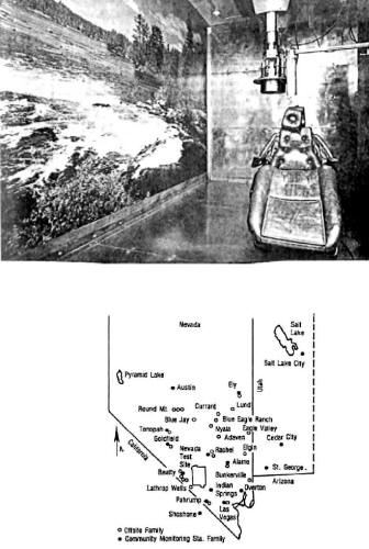
ILLUSTRATION 45
The Environmental Protection Agency tracks the
migration of atomic particles from the Nevada Test Site into the animals
and humans of the surrounding environment. This map, modified from an EPAmap, shows the location of about 40 families who are brought into the
EPA twice a year for whole-body analysis. Part of their examination
takes place in the reclining chair pictured in the photograph. The
machinery which hangs from the ceiling performs a whole-body scan of the
subject. Source: U.S. Congress, Office of Technology Assessment, The
Containment of Underground Nuclear Explosions, OTA-ISC-414 (Washington,
DC: US Government Printing Office, October 1989).
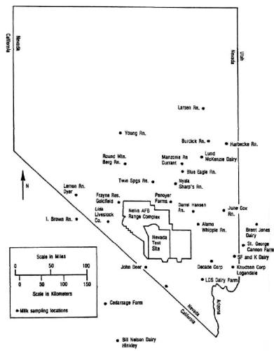
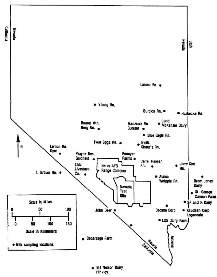
ILLUSTRATION 46
Samples of raw milk are collected each month
from about 25 farms surrounding the Nevada Test Site. Source: U.S.
Congress, Office of Technology Assessment, The Containment of
Underground Nuclear Explosions, OTAISC-414 (Washington, DC: US
Government Printing Office, October 1989).
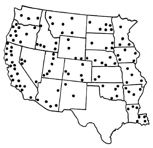
ILLUSTRATION 47
Is the government more concerned about nuclear
pollution of the environment than it lets on? Every year it collects
milk samples for analysis from its standby milk surveillance network,
which is made up of all of the major milksheds west of the Mississippi
River. Source: U.S. Congress, Office of Technology Assessment, The
Containment of Underground Nuclear Explosions. OTA-ISC-414 (Washington,
DC: US Government Printing Office, October 1989).
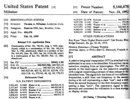
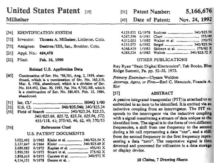
BACKGROUND AND OBJECTS OF THE INVENTION
The primary object of this invention is to provide a system for identifying
an object, animal or person consisting essentially of two units, one being a
passive integrated transponder (PIT) which is carried by or embedded in the
thing or animal to be identified and which responds to interrogation with an
identifying code, and the other unit being an interrogator-reader separate
from the PIT.
Heretofore, in identification device systems, there is and
other flaky characters, and nothing more. In that way, the Pentagon could
carry out its underground agenda and prying eyes would be deflected by the
threat of public humiliation and ridicule.
ILLUSTRATION 48
This U.S. patent describes the inner
electronic workings of an injectable transponder. Note the detail from
this patent, which says "The primary object of this invention is to
provide a system for identifying an object, animal of person..." More
than one company in the U.S. now sells injectable electronic IDs They
are commonly used to identify livestock or companion animals.

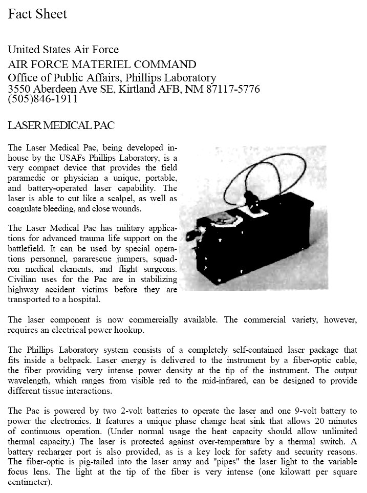
ILLUSTRATION 49
This medical laser is portable enough to be
worn on a belt pack around the waist, and can be used to either make
cuts or close wounds. According to the Air Force, "It can be used by
special operations personnel..." Reprinted with permission from Phillips
Laboratory, Office of Public Affairs, Kirtland Air Force Base, NM.
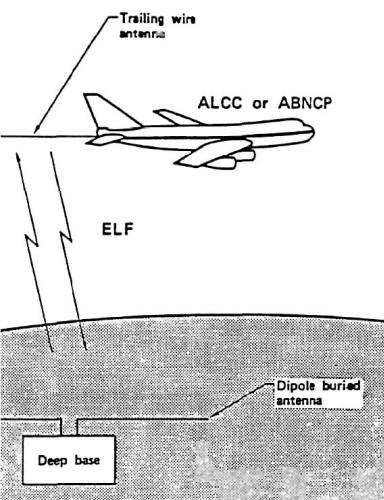
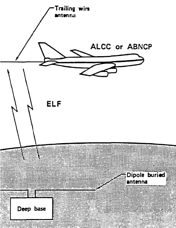
ILLUSTRATION 50
Communication from a deep underground base
could transmit through conventional ground lines; through a satellite or
microwave dish; or ~ as this illustration shows ~ in a way that would be
invisible to a surface observer. Extremely Low Frequency (ELF)
communications transmit through the earth itself, using a widely-spread
underground antenna system. Source: Decision Analysis Methodology
Applied to Deep Base Communications, Subtask Progress Report for 1985
Prepared for the Headquarters, Ballistic Missile Office, USAF. Document
ID Nos.-.AFMIPR No. FY 7653-85-00305; UCID -20848; and DE87 000945.
In any event, the evidence I have presented above is the closest I can come
to documenting an actual, covert, underground tunnel system in the western
states.
This system may or may not exist.
The Department of Transportation Tunnel Plans
I have found less documentation for
the Department of Transportation's planned tunnel system in the Northeast.
I
was able to find a few documents, however, including one lengthy report that
spoke forthrightly about constructing what it referred to as a "High Speed
Ground Transportation (HSGT) system in the Northeast Corridor."
Presumably
the system would be for the use of commuters, although just who would use
the tunnels was left somewhat ambiguous. Vague reference to "vehicles" that
would use the system also left some doubt as to the mode of transportation
that was to have been employed. In the following chapter on unconventional
tunneling technologies I present documentation on a flame-jet tunneling
system intended for constructing a deeply buried, high speed rail tunnel
system in the Northeast.
These two sets of documents would appear to be
describing plans for one and the same system, the more so since they were
both published in the same year (1968).
As set forth in the document, the tunnel system could have ranged as deeply
as 3,500 ft. underground. It was to have been at least 500 ft. underground
when cutting beneath major rivers, with the exception of the Hudson, under
which it was to cross at a depth of not less than 750 ft.
Diameters for
tunnels in the system were not specified, 81 though a range of excavated
diameters (not to be confused with finished diameters, which would be
somewhat less due to the tunnel lining and support) all the way from 8 ft.
to 40 ft. was discussed. Specifically, diameters of 8 ft., 20 ft., 30 ft.
and 40 ft. were mentioned.
An obvious question is: why would the DOT bother to construct an inter-city
tunnel system that would be less than 8 ft. in diameter? It hardly makes
sense, except as an auxiliary or utility tunnel for a larger diameter
companion tunnel. The larger diameters, of course, could conceivably
accommodate some sort of rapid rail, or magnetic levitation train.16
Terminals were to range in size between 10,000 and 1,000,000 sq ft. in area,
and to have multiple levels. They were slated to be located at least 300
ft., and in some cases, 500 ft. or more underground. They were to have been
as much as 2,000 ft. long.
The terminals were to have been situated under or near: Washington, DC;
Baltimore, Maryland; Philadelphia, Pennsylvania; New York, New York; New
Haven, Connecticut; Hartford, Connecticut; and Boston, Massachusetts. The
plans also called for at least one deep shaft between each city to connect
with the system.
The shafts were to be vertical, and quite large and deep
-extending as far down as 3,500 ft., if necessary, and having a
cross-section of between 50 and 500 sq. ft.17
Plans vs. Real Tunnels
Once again, the question arises: has
this system been built?
The planning study is certainly very interesting. In
fact, it is just the sort of obscure document you would expect to find if,
indeed, a secret tunnel system were being planned and/or built by the U.S.
government.
But the reader must be clear on the fact that plans are one thing, and
actual tunnels quite another. Sometimes plans culminate in completed
construction projects; at other times, plans are never concretely realized
and are relegated instead to a dusty shelf in the government documents
collection.
I simply do not know if the government (or some other organization) has
secretly built a high speed transportation tunnel system in the northeastern
corridor of the United States. If you do, please send me the relevant
documentation.
Back to
Contents